Ultra-Low Voltage Intel® Celeron® Processor — 650 MHz and 400 MHz
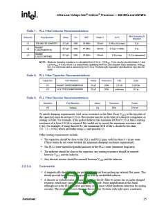
Table 7. PLL Filter Inductor Recommendations
Min Damping R
Needed
Inductor
Part Number
Value
Tol
SRF
Rated I
DCR
L1
L2
TDK MLF2012A4R7KT
4.7 µH
4.7 µH
10%
10%
35 MHz
47 MHz
30 mA
30 mA
0.56 Ω (1Ω max)
0.7 Ω (+/-50%)
0 Ω
0 Ω
Murata*
LQG21N4R7K10
Murata*
LQG21C4R7N00
L3
4.7 µH
30%
35 MHz
30 mA
0.3 Ω max
0.2 Ω (assumed)
NOTE: Minimum damping resistance is calculated from 0.35 Ω – DCRmin. From vendor provided data, L1 and
L2 DCRmin is 0.4 Ω and 0.5 Ω respectively, qualifying them for zero required trace resistance. DCRmin
for L3 is not known and is assumed to be 0.15 Ω. Products with equivalent specifications may also be
used.
Table 8. PLL Filter Capacitor Recommendations
Capacitor
Part Number
Value
Tolerance
ESL
ESR
C1
C2
Kemet* T495D336M016AS
AVX TPSD336M020S0200
33 µF
33 µF
20%
20%
2.5 nH
0.225 Ω
0.2 Ω
unknown
Table 9. PLL Filter Resistor Recommendations
Resistor
Part Number
Value
1Ω
Tolerance
10%
Power
R1
Various
1/16 W
To satisfy damping requirements, total series resistance in the filter (from VCCT to the top plate of
the capacitor) must be at least 0.35 Ω. This resistor may be in the form of a discrete component, or
routing, or both. For example, if the picked inductor has minimum DCR of 0.25 Ω, then a routing
resistance of at least 0.10 Ω is required. Be careful not to exceed the maximum resistance rule
(2 Ω). For example, if using discrete R1, the maximum DCR of the L should be less than
2.0 - 1.1 = 0.9 Ω, which precludes using L2 and possibly L1.
Other routing requirements include:
• The capacitor should be close to the PLL1 and PLL2 pins, with less than 0.1 Ω per route
(These routes do not count towards the minimum damping resistance requirement).
• The PLL2 route should be parallel and next to the PLL1 route (minimize loop area).
• The inductor should be close to the capacitor; any routing resistance should be inserted
between VCCT and the inductor.
• Any discrete resistor should be inserted between VCCT and the inductor.
3.2.3.4
Comments
• A magnetically shielded inductor protects the circuit from picking up external flux noise. This
should provide better timing margins than with an unshielded inductor.
• A discrete or routed resistor is required because the LC filter by nature has an under-damped
response, which may cause resonance at the LC pole. Noise amplification at this band,
although not in the PLL-sensitive spectrum, could cause a fatal headroom reduction for analog
circuitry. The resistor serves to dampen the response. Systems with tight space constraints
Datasheet
25

 INTEL [ INTEL ]