Ultra-Low Voltage Intel® Celeron® Processor — 650 MHz and 400 MHz
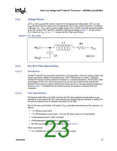
• The filter should support a DC current of at least 30 mA
• The DC voltage drop from V
to PLL1 should be less than 60 mV, which in practice implies
series resistance of less than 2 Ω. This also means that the pass band (from DC to 1 Hz)
CCT
attenuation below 0.43 dB for V = 1.25 V.
CCT
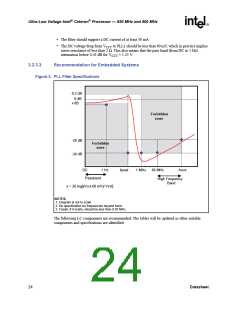
3.2.3.3
Recommendation for Embedded Systems
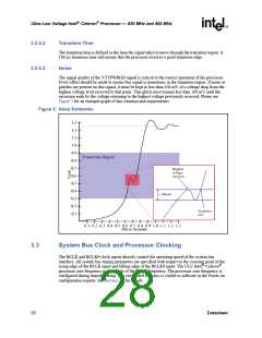
Figure 3. PLL Filter Specifications
0.2 dB
0 dB
x dB
Forbidden
zone
-28 dB
-34 dB
Forbidden
zone
DC
Passband
x = 20.log[(Vcct-60 mV)/ Vcct]
1 Hz
fpeak
1 MHz
66 MHz
fcore
High Frequency
Band
NOTES:
1. Diagram is not to scale
2. No specification for frequencies beyond fcore.
3. Fpeak, if it exists, should be less than 0.05 MHz.
The following LC components are recommended. The tables will be updated as other suitable
components and specifications are identified.
24
Datasheet

 INTEL [ INTEL ]