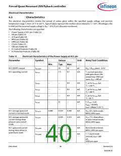
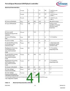
Forced Quasi Resonant ZVS flyback controller
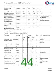
Electrical Characteristics
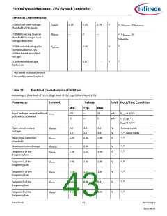
1) 3)
Burst mode entry
threshold
0.175
0.209
0.242
V
,
VMFIOBMEN
3)
Internal pull-up resistor
8.8
11
13.2
kΩ
RMFIOPU
1), 3)
Burst wake-up threshold
during burst-off phase
0.231
0.266
0.300
V
VMFIOBMWK
Minimum input pulse
width for burst wake-up
300
—
—
ns
µs
1), shorter pulses will
be suppressed
tMFIOBMWKPW
tMFIOBMWK
1)
Time between burst
wake-up and the first
burst sequence pulse
—
26.6
32
,
dVMFIO/dt = 100 mV/µs
1) 3)
Burst-off entering
threshold during burst-
on phase
0.175
0.231
0.209
0.266
0.242
0.300
V
V
,
VMFIOBMPA
1) 3)
BM exit threshold
,
VMFIOBMEX
Not tested in production test.
During burst mode, auto restart and latch mode operation.
See configuration Chapter 5.
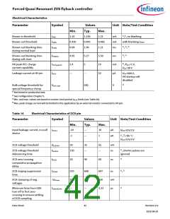
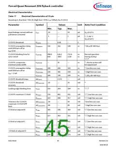
Table 16
Electrical Characteristics of GPIO pin
Symbol
Parameter
Values
Typ.
Unit
Note/Test Condition
Min.
Max.
Input leakage current without
pull device activated
-10
-1
—
—
10
1
µA
µA
IGPIOLK
V
GPIO=0 V/3 V
1), TJ=85˚C
GPIO=0 V/3 V
V
Open circuit output
voltage
3.0
3.3
3.6
V
VGPIOOC
1
Input capacitance
—
—
—
—
—
10
1.0
—
pF
V
CGPIOIN
VGPIOIL
VGPIOIH
-IGPIOLPU
Threshold for logic “0”
Threshold for logic “1”
—
2.0
30
V
2) at VGPIOIL(max)
Low input pull-up
current
90
µA
Output sink current
—
—
—
—
—
—
2
mA
mA
ns
IGPIOSNKOL
-IGPIOSRCOH
tGPIORISE
Output source current
Output rise time (0 → 1)
2
50
20 pF load, push/pull
output
Output fall time (1 → 0)
—
—
50
ns
20 pF load, push/pull
output
tGPIOFALL
1) Not tested in production test.
2) Currents flowing out of the device (DUT) are marked with a negative sign in the ‘Symbol’ column
Data Sheet
44
Revision 2.0
2020-08-20

 INFINEON [ Infineon ]