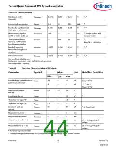
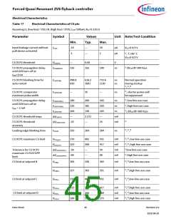
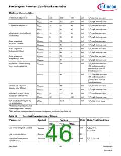
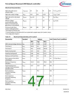
Forced Quasi Resonant ZVS flyback controller
Electrical Characteristics
1)
1)
Burst sequence:
4th and consecutive pulse
switching frequency
—
50.2
—
kHz
kHz
fSWBSP4
Switching frequency 1st
pulse directly after BM exit
1) Not tested in production test.
132.3
139.1
146.6
fSWBMEXHV
2) The master clock period is the base for all time measurements without stand-by. Relative tolerances of all performed time
measurements are same as with tMCLK
.
3) The stand-by clock is the base for all time related characteristics during stand-by operation.
4) Phase for loading the OTP content to the internal RAM
Table 20
Electrical Characteristics of IC Protection Features
Parameter
Symbol
Values
Unit Note/Test Condition
Min.
Typ.
Max.
1) 2)
Auto-restart bang-bang mode
off-time
455
500
556
ms
,
tBBoffAR
1) 2)
Auto-restart time
2.73
29.7
3
—
s
,
tAR
1) 3)
Blanking time of open-loop
timer
31.3
33
ms
,
tMFIOH
V
MFIO>VMFIOOLP
1),4)
Over-temperature detection
122
130
-
°C
TJOTP
tJOTP
1) 3)
Over-temperature blanking
time
9.90
10.50
11.10
ms
,
1)
Over-temperature
Hysteresis
-
20
-
°C
TJHYS_OTP
1) Not tested in production test.
2) Min. and max. values are based on stand-by clock period tSTBCLK limits (see Table 20).
3) Min. and max. values are based on master clock period tMCLK (see Table 20).
4)
The recommended temp is below 125 ˚C, above this temperature, IC function cannot be guaranteed, Customer should guarantee
the design will never exceed the 125 ˚C of IC die temperature.
Data Sheet
48
Revision 2.0
2020-08-20

 INFINEON [ Infineon ]