Forced Quasi Resonant ZVS flyback controller
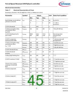
Electrical Characteristics
—
—
—
—
—
—
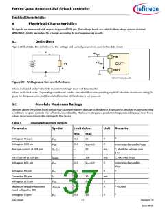
1.2
1.0
0.8
mA
mA
mA
IVCCquBM3
IVCCquBM4
IVCCquBM5
1), as for IVCCquBM2
TJ=110˚C
,
,
,
1), as for IVCCquBM2
TJ=100˚C
1), as for IVCCquBM2
TJ=85˚C
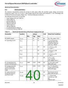
VCC turn-on threshold
VCC turn-off threshold
19
20.5
7.2
21.5
7.56
V
V
VVCCon
VVCCoff
dVVCC/dt =0.2 V/ms
6.84
During normal
operation, IC latched
and auto-restart
break time
1)
VCC turn-on/off
hysteresis during normal
operation
—
13.3
—
—
V
VVCChysOP
VCC turn-off blanking
time
550
—
ns
1), 1 V overdrive
tVCCoff
1)
VCC turn-on delay
—
—
2
µs
V
tVCCon
VCC threshold for turning
on HV startup cell in
protection mode
8.5
9
9.5
1), bang-bang mode
during auto-restart
and latch mode
VVCCBBon
Blanking time for turning
on HV startup cell in
auto-restart and latch
mode
0.6
19
—
2.2
µs
V
1), 1 V overdrive,
bang-bang mode
tVCCBBon
VVCCBBoff
tVCCBBoff
VCC threshold for turning
off HV startup cell in
auto-restart and latch
mode
20.5
—
21.5
2.4
Blanking time for turning
off HV startup cell in
auto-restart and latch
mode
0.7
µs
1), 1 V overdrive,
bang-bang mode
1) 3)
VCC brown-in threshold
8.4
9.1
9.7
V
V
,
VVCCBI
1) 3)
VCC Over-Voltage
Protection threshold
20.9
21.8
22.7
,
VVCCOVP
1) 3)
VCC Over-Voltage
tVCCOVPBLK
—
100
—
µs
,
Protection Blanking time
1) Not tested in production test.
2) Current value is based on the sum of external sink current IMFIO and IC quiescent current IVCCquBM1
3) See configuration Chapter5
.
Table 13
Electrical Characteristics of HV pin
Data Sheet
41
Revision 2.0
2020-08-20

 INFINEON [ Infineon ]