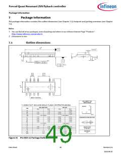
Forced Quasi Resonant ZVS flyback controller
Electrical Characteristics
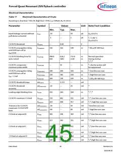
Table 17
Electrical Characteristics of CS pin
Assuming LL (low line) =72V, HL (high line) =372V, LPRI=200uH, RCS=0.135 Ω
Parameter
Symbol
Values
Unit Note/Test Condition
Min.
Typ.
Max.
Input leakage current without
pull device activated
-10
—
10
µA
µA
ICSLK
VCS=0 V/3 V
1), TJ=85˚C
VCS=0 V/3 V
-1
—
1
CS OCP2 threshold
—
0.60
155
—
V
VCSOCP2
CS OCP2 propagation delay
until GD0 turn-off at
125
190
ns
1) dVCS/dt=100 V/µs
tCSGD0OCP2
IGD0>2mA
CS OCP2 blanking time for
auto-restart
498.8
810
616.2
1001
733.6
1192
ns
ns
Normal operation
During startup
1), 2), 3)
tCSOCP2BL
CS OCP1 comparator
minimum pulse width
—
35
—
ns
1), shorter pulses will
be suppressed
tCSOCP1PW
CS OCP1 propagation delay
until GD0 turn-off at
180
120
100
—
260
185
130
2.371
—
345
250
165
—
ns
1), low line use case
1), high line use case
1), dVCS/dt=100 V/µs
tCSOCP1PDLL
tCSOCP1PDHL
tCSOCP1PD
ns
IGD0 > 2 mA
ns
CS OCP1 threshold steps
mV
mV
∆VCSOCP1
1)
CS OCP1 threshold
accuracy
-25
25
∆VCSOCP1THR
Leading edge blanking time
255
269
284
ns
1), 2), 3)
tCSLEB
CS OCP1 maximum CS limit
370
323
-50
-60
402
368
—
431
417
50
mV
mV
mV
mV
1), 2), low line use case
1), 2), high line use case
1),low line use case
1), high line use case
VCSmaxLL
VCSmaxHL
Tolerance for CS OCP1
maximum CS FASTOPP
limit
∆VCSFASTOPPLL
∆VCSFASTOPPHL
—
60
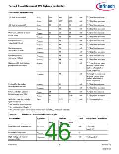
CS limit at setpoint B
305
257
370
336
303
402
365
351
431
mV
mV
mV
1), 2),low line use case
1), 2),high line use case
1), 2),low line use case
VCSBLL
VCSBHL
VCSCLL
CS limit at setpoint C
CS limit at setpoint D
323
229
189
368
260
227
417
289
275
mV
mV
mV
1), 2),high line use case
1), 2),low line use case
1), 2),high line use case
VCSCHL
VCSCLL
VCSCHL
Data Sheet
45
Revision 2.0
2020-08-20

 INFINEON [ Infineon ]