IMW120R020M1H
™
CoolSiC 1200 V SiC Trench MOSFET
4 Characteristics diagrams
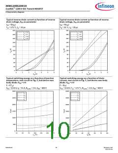
Typical switching energy losses as a function of gate
Typical switching times as a function of gate
resistance, test circuit in Fig. F, 2nd device own body resistance, test circuit in Fig. F, 2nd device own body
diode: VGS = 0 V
E = f(RG,ext
diode: VGS = 0 V
t = f(RG,ext
)
)
VGS = 0/18 V, ID = 41 A, Tvj = °C, VDD = 800 V
VGS = 0/18 V, ID = 41 A, Tvj = 175 °C, VDD = 800 V
9000
400
350
300
250
200
150
100
50
6000
3000
0
0
0
10
20
30
40
50
0
10
20
30
40
50
Typical reverse recovery charge as a function of
Typical reverse recovery current as a function of
revere drain current slope, test circuit in Fig. F, 2nd
device own body diode: VGS = 0 V
reverse drain current slope, test circuit in Fig. F, 2nd
device own body diode: VGS = 0 V
Qfr = f(diSD/dt )
Ifrm = f(diSD/dt )
VGS = 0/18 V, ISD = 41 A, VDD = 800 V
VGS = 0/18 V, ISD = 41 A, VDD = 800 V
0.8
0.7
0.6
0.5
0.4
0.3
0.2
0.1
0.0
30
25
20
15
10
5
0
0
1000
2000
3000
4000
5000
6000
0
1000
2000
3000
4000
5000
Datasheet
11
Revision 1.30
2023-05-08

 INFINEON [ Infineon ]