AN985B/BX
Registers and Descriptors Description
Memory Base Address
MBA_CR5
Memory Base Address
Offset
14H
Reset Value
0000 0000H
ꢀꢁ ꢀꢂ ꢃꢄ ꢃꢅ ꢃꢆ ꢃꢇ ꢃꢈ ꢃꢉ ꢃꢀ ꢃꢃ ꢃꢁ ꢃꢂ ꢁꢄ ꢁꢅ ꢁꢆ ꢁꢇ ꢁꢈ ꢁꢉ ꢁꢀ ꢁꢃ ꢁꢁ ꢁꢂ ꢄ
ꢅ
ꢆ
ꢇ
ꢈ
5HV
UR
ꢉ
ꢀ
ꢃ
ꢁ
ꢂ
,2
6,
0%$
UZ
UR
Field
Bits
Type
Description
MBA
31:10
rw
Memory Base Address
This value indicates the base address of CARDBUS control and status
register (CSR0~28).
Res
IOSI
9:1
0
ro
ro
Reserved
Memory Space Indicator
1B
, means that the configuration registers map into the I/O space
Card Information Structure
This register is used to point one of the possible address spaces where the CIS begins. This register is designed
for CARDBUS environment. It’s data is auto-loaded from the serial EEPROM after power on or hardware reset.
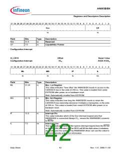
CIS_CR10
Card Information Structure
Offset
28H
Reset Value
From EEPROMH
ꢀꢁ ꢀꢂ ꢃꢄ ꢃꢅ ꢃꢆ ꢃꢇ ꢃꢈ ꢃꢉ ꢃꢀ ꢃꢃ ꢃꢁ ꢃꢂ ꢁꢄ ꢁꢅ ꢁꢆ ꢁꢇ ꢁꢈ ꢁꢉ ꢁꢀ ꢁꢃ ꢁꢁ ꢁꢂ ꢄ
ꢅ ꢆ ꢇ ꢈ ꢉ ꢀ ꢃ ꢁ ꢂ
520
$62
$,
UR
UR
UR
Field
ROM
Bits
31:30
Type
ro
Description
ROM Image
This ROM image value is applied when the CIS is stored in a boot ROM.
This value is loaded from serial EEPROM.
ASO
AI
29:4
3:0
ro
ro
Address Space Offset
This value indicates the offset within the address space. The address
space is specified by address space indicator(bit 2~0 of CR10).
Address Space Indicator
This value indicates the location where the CIS address space begins.
111B , means that the CIS begins in the boot ROM space.
othersB, makes all the bits of CIS reset to 0
Data Sheet
40
Rev. 1.51, 2005-11-30

 INFINEON [ Infineon ]