Preliminary
HT48R06A-1
request flag (EIF; bit 4 of INTC) will be set.
When the interrupt is enabled, the stack is not
full and the external interrupt is active, a sub-
routine call to location 04H will occur. The in-
terrupt request flag (EIF) and EMI bits will be
cleared to disable other interrupts.
following table shows the priority that is ap-
plied. These can be masked by resetting the
EMI bit.
No. Interrupt Source Priority Vector
a
b
External Interrupt
1
2
04H
08H
The internal timer/event counter interrupt is
initialized by setting the timer/event counter
interrupt request flag (TF; bit 5 of INTC),
caused by a timer overflow. When the interrupt
is enabled, the stack is not full and the TF bit is
set, a subroutine call to location 08H will occur.
The related interrupt request flag (TF) will be
reset and the EMI bit cleared to disable further
interrupts.
Timer/event
Counter Overflow
The timer/event counter interrupt request flag
(TF), external interrupt request flag (EIF), en-
able timer/event counter bit (ETI), enable ex-
ternal interrupt bit (EEI) and enable master
interrupt bit (EMI) constitute an interrupt con-
trol register (INTC) which is located at 0BH in
the data memory. EMI, EEI, ETI are used to
control the enabling/disabling of interrupts.
These bits prevent the requested interrupt
from being serviced. Once the interrupt request
flags (TF, EIF) are set, they will remain in the
INTC register until the interrupts are serviced
or cleared by a software instruction.
During the execution of an interrupt subroutine,
other interrupt acknowledgments are held until
the "RETI" instruction is executed or the EMI
bit and the related interrupt control bit are set to
1 (of course, if the stack is not full). To return
from the interrupt subroutine, "RET" or "RETI"
may be invoked. RETI will set the EMI bit to en-
able an interrupt service, but RET will not.
It is recommended that a program does not
use the "CALL subroutine" within the inter-
rupt subroutine. Interrupts often occur in an
unpredictable manner or need to be serviced
immediately in some applications. If only one
stack is left and enabling the interrupt is not
well controlled, the original control sequence will
Interrupts, occurring in the interval between
the rising edges of two consecutive T2 pulses,
will be serviced on the latter of the two T2
pulses, if the corresponding interrupts are en-
abled. In the case of simultaneous requests the
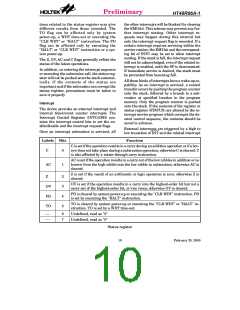
Register Bit No.
Label
Function
Controls the master (global) interrupt
(1= enabled; 0= disabled)
0
EMI
Controls the external interrupt
(1= enabled; 0= disabled)
1
EEI
Controls the timer/event counter interrupt
(1= enabled; 0= disabled)
2
ETI
¾
INTC
3
(0BH)
Unused bit, read as "0"
External interrupt request flag
(1= active; 0= inactive)
4
EIF
Internal timer/event counter request flag
(1= active; 0= inactive)
5
TF
6
7
Unused bit, read as "0"
Unused bit, read as "0"
¾
¾
INTC register
11
February 25, 2000

 HOLTEK [ HOLTEK SEMICONDUCTOR INC ]