Preliminary
HT48R06A-1
be damaged once the "CALL" operates in the in-
terrupt subroutine.
OSC1 and OSC2 is needed to provide the feed-
back and phase shift required for the oscillator,
and no other external components are required.
Instead of a crystal, a resonator can also be con-
nected between OSC1 and OSC2 to get a fre-
quency reference, but two external capacitors
in OSC1 and OSC2 are required (If the oscillat-
ing frequency is less than 1MHz).
Oscillator configuration
There are two oscillator circuits in the
microcontroller.
V
D
D
The WDT oscillator is a free running on-chip RC
oscillator, and no external components are re-
quired. Even if the system enters the power down
mode, the system clock is stopped, but the WDT
oscillator still works with a period of approxi-
mately 65ms/5V. The WDT oscillator can be dis-
n
O
S
C
1
O
O
S
S
C
C
1
2
4
7
0
p
F
f
S
Y
S
O
S
C
2
N
M
O
S
O
p
e
n
D
r
a
i
C
r
y
s
t
a
l
O
s
c
i
l
l
a
t
o
r
R
C
O
s
c
l
l
a
t
r
abled by ROM codei option to o conserve power.
System oscillator
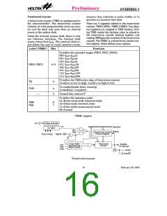
Watchdog timer - WDT
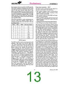
The clock source of WDT is implemented by a
dedicated RC oscillator (WDT oscillator) or in-
struction clock (system clock divided by 4), de-
cided by ROM code option. This timer is
designed to prevent a software malfunction or
sequence from jumping to an unknown location
with unpredictable results. The watchdog
timer can be disabled by a ROM code option. If
the watchdog timer is disabled, all the execu-
tions related to the WDT result in no operation.
Both are designed for system clocks, namely
the RC oscillator and the Crystal oscillator,
which are determined by the ROM code option.
No matter what oscillator type is selected, the
signal provides the system clock. The HALT
mode stops the system oscillator and ignores an
external signal to conserve power.
If an RC oscillator is used, an external resistor
between OSC1 and VDD is required and the
resistance must range from 51kW to 1MW. The
system clock, divided by 4, is available on
OSC2, which can be used to synchronize exter-
nal logic. The RC oscillator provides the most
cost effective solution. However, the frequency
of oscillation may vary with VDD, tempera-
tures and the chip itself due to process varia-
tions. It is, therefore, not suitable for timing
sensitive operations where an accurate oscilla-
tor frequency is desired.
Once the internal WDT oscillator (RC oscillator
with a period of 65ms/5V normally) is selected, it
is first divided by 256 (8-stage) to get the nomi-
nal time-out period of approximately
16.6ms/5V. This time-out period may vary with
temperatures, VDD and process variations. By
invoking the WDT prescaler, longer time-out
periods can be realized. Writing data to WS2,
WS1, WS0 (bit 2,1,0 of the WDTS) can give differ-
ent time-out periods. If WS2, WS1, and WS0 are
all equal to 1, the division ratio is up to 1:128, and
If the Crystal oscillator is used, a crystal across
S
y
s
t
e
m
C
l
o
c
k
/
4
W
D
T
P
r
e
s
c
a
l
e
r
R
O
M
C
o
d
e
8
-
b
i
t
C
o
u
7
n
-
b
t
e
i
t
r
C
o
u
n
t
e
r
O
p
t
i
o
n
S
e
l
e
c
t
W
D
T
O
S
C
8
-
t
o
-
1
M
U
X
S
W
0
~
W
S
2
W
D
T
T
i
m
e
-
o
u
t
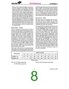
Watchdog timer
12
February 25, 2000

 HOLTEK [ HOLTEK SEMICONDUCTOR INC ]