Preliminary
HT48R06A-1
the maximum time-out period is 2.2s/5V seconds.
Power down operation - HALT
If the WDT oscillator is disabled, the WDT clock
may still come from the instruction clock and op-
erate in the same manner except that in the
HALT state the WDT may stop counting and lose
its protecting purpose. In this situation the logic
can only be restarted by external logic. The high
nibble and bit 3 of the WDTS are reserved for
user's defined flags, which can be used to indicate
some specified status.
The HALT mode is initialized by the "HALT" in-
struction and results in the following...
·
The system oscillator will be turned off but
the WDT oscillator keeps running (if the
WDT oscillator is selected).
·
·
The contents of the on chip RAM and regis-
ters remain unchanged.
WDT and WDT prescaler will be cleared and
recounted again (if the WDT clock is from the
WDT oscillator).
If the device operates in a noisy environment, us-
ing the on-chip RC oscillator (WDT OSC) is
strongly recommended, since the HALT will stop
the system clock.
·
·
AlloftheI/Oportsmaintaintheiroriginalstatus.
The PD flag is set and the TO flag is cleared.
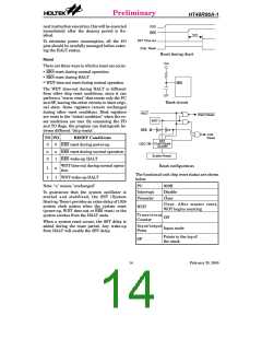
The system can leave the HALT mode by means
of an external reset, an interrupt, an external
falling edge signal on port A or a WDT overflow.
An external reset causes a device initialization
and the WDT overflow performs a "warm re-
set". After the TO and PD flags are examined,
the reason for chip reset can be determined.
The PD flag is cleared by system power-up or
executing the "CLR WDT" instruction and is set
when executing the "HALT" instruction. The
TO flag is set if the WDT time-out occurs, and
causes a wake-up that only resets the PC and
SP; the others keep their original status.
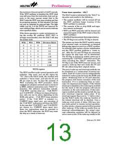
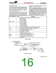
WS2
WS1
WS0
Division Ratio
0
0
0
0
1
1
1
1
0
0
1
1
0
0
1
1
0
1
0
1
0
1
0
1
1:1
1:2
1:4
1:8
1:16
1:32
1:64
1:128
WDTS register
The port A wake-up and interrupt methods can
be considered as a continuation of normal exe-
cution. Each bit in port A can be independently
selected to wake up the device by the ROM code
option. Awakening from an I/O port stimulus,
the program will resume execution of the next
instruction. If it is awakening from an inter-
rupt, two sequences may happen. If the related
interrupt is disabled or the interrupt is enabled
but the stack is full, the program will resume
execution at the next instruction. If the inter-
rupt is enabled and the stack is not full, the reg-
ular interrupt response takes place. If an
interrupt request flag is set to "1" before enter-
ing the HALT mode, the wake-up function of
the related interrupt will be disabled. Once a
wake-up event occurs, it takes 1024 tSYS (sys-
tem clock period) to resume normal operation.
In other words, a dummy period will be inserted
after wake-up. If the wake-up results from an
interrupt acknowledgment, the actual inter-
rupt subroutine execution will be delayed by
one or more cycles. If the wake-up results in the
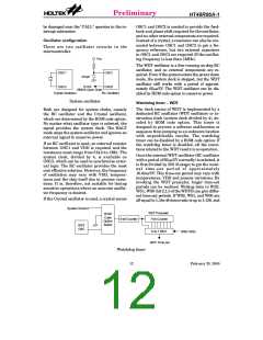
The WDT overflow under normal operation will
initialize "chip reset" and set the status bit
"TO". But in the HALT mode, the overflow will
initialize a ²warm reset², and only the PC and
SP are reset to zero. To clear the contents of
WDT (including the WDT prescaler), three
methods are adopted; external reset (a low level
to RES), software instruction and a "HALT" in-
struction. The software instruction include
"CLR WDT" and the other set - "CLR WDT1"
and "CLR WDT2". Of these two types of instruc-
tion, only one can be active depending on the
ROM code option - "CLR WDT times selection
option". If the "CLR WDT" is selected (i.e.
CLRWDT times equal one), any execution of
the "CLR WDT" instruction will clear the WDT.
In the case that "CLR WDT1" and "CLR WDT2"
are chosen (i.e. CLRWDT times equal two),
these two instructions must be executed to
clear the WDT; otherwise, the WDT may reset
the chip as a result of time-out.
13
February 25, 2000

 HOLTEK [ HOLTEK SEMICONDUCTOR INC ]