Preliminary
HT48R06A-1
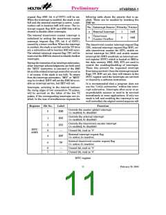
0
0
0
0
0
0
0
4
8
H
H
H
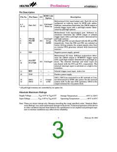
Certain locations in the program memory are
reserved for special usage:
D
e
v
i
c
e
I
n
i
t
i
a
l
i
z
a
t
i
o
n
P
r
o
g
r
a
m
·
Location 000H
E
x
t
e
r
n
a
l
I
n
t
e
r
r
u
p
t
S
u
b
r
o
u
t
i
n
e
This area is reserved for program initializa-
tion. After chip reset, the program always be-
gins execution at location 000H.
T
i
m
e
r
/
E
v
e
n
t
C
o
u
n
t
e
r
I
n
t
e
r
r
u
p
t
S
u
P
M
r
o
g
r
a
m
·
Location 004H
e
m
o
r
y
n
0
F
0
H
L
L
o
o
o
o
k
k
-
-
u
u
p
p
T
T
a
a
b
b
l
l
e
e
(
(
2
2
5
5
6
6
w
o
r
d
s
)
This area is reserved for the external inter-
rupt service program. If the INT input pin is
activated, the interrupt is enabled and the
stack is not full, the program begins execution
at location 004H.
n
F
H
w
o
r
d
s
)
3
F
F
H
·
·
Location 008H
1
4
b
i
t
s
This area is reserved for the timer/event coun-
ter interrupt service program. If a timer inter-
rupt results from a timer/event counter
overflow, and if the interrupt is enabled and the
stack is not full, the program begins execution
at location 008H.
N
o
t
e
:
n
r
a
n
g
e
s
f
r
o
m
0
t
o
3
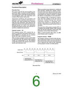
Program memory
the lower-order byte in the table is
well-defined, the other bits of the table word
are transferred to the lower portion of TBLH,
and the remaining 2 bits are read as "0". The
Table Higher-order byte register (TBLH) is
read only. The table pointer (TBLP) is a
read/write register (07H), which indicates the
table location. Before accessing the table, the
location must be placed in TBLP. The TBLH
is read only and cannot be restored. If the
main routine and the ISR (Interrupt Service
Table location
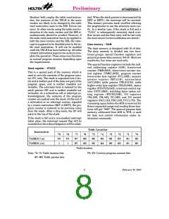
Any location in the PROM space can be used
as look-up tables. The instructions "TABRDC
[m]" (the current page, 1 page=256 words)
and "TABRDL [m]" (the last page) transfer
the contents of the lower-order byte to the
specified data memory, and the higher-order
byte to TBLH (08H). Only the destination of
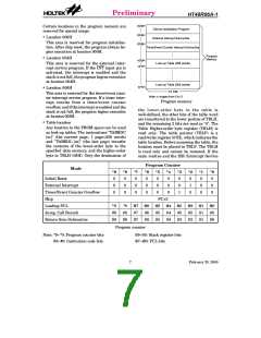
Program Counter
Mode
*9
0
*8
*7
0
*6
0
*5
0
*4
0
*3
0
*2
0
*1
0
*0
0
Initial Reset
0
0
0
External Interrupt
Timer/Event Counter Overflow
Skip
0
0
0
0
0
0
1
0
0
0
0
0
0
0
1
0
0
0
PC+2
Loading PCL
*9
#9
S9
*8
#8
S8
@7
#7
S7
@6
#6
S6
@5
#5
S5
@4
#4
S4
@3
#3
S3
@2
#2
S2
@1
#1
S1
@0
#0
S0
Jump, Call Branch
Return from Subroutine
Program counter
Note: *9~*0: Program counter bits
#9~#0: Instruction code bits
S9~S0: Stack register bits
@7~@0: PCL bits
7
February 25, 2000

 HOLTEK [ HOLTEK SEMICONDUCTOR INC ]