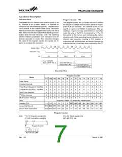
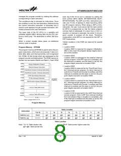
HT46RU25/HT46CU25
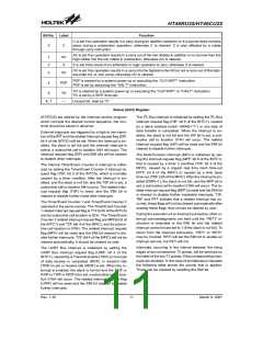
Bit No. Label
Function
C is set if an operation results in a carry during an addition operation or if a borrow does not take
place during a subtraction operation; otherwise C is cleared. C is also affected by a rotate
through carry instruction.
0
C
AC is set if an operation results in a carry out of the low nibbles in addition or no borrow from the
high nibble into the low nibble in subtraction; otherwise AC is cleared.
1
2
3
AC
Z
Z is set if the result of an arithmetic or logic operation is zero; otherwise Z is cleared.
OV is set if an operation results in a carry into the highest-order bit but not a carry out of the high-
est-order bit, or vice versa; otherwise OV is cleared.
OV
PDF is cleared by a system power-up or executing the ²CLR WDT² instruction.
PDF is set by executing the ²HALT² instruction.
4
PDF
TO is cleared by a system power-up or executing the ²CLR WDT² or ²HALT² instruction.
TO is set by a WDT time-out.
5
TO
6, 7
¾
Unused bit, read as ²0²
Status (0AH) Register
(STATUS) are altered by the interrupt service program
which corrupts the desired control sequence, the con-
tents should be saved in advance.
The I2C Bus interrupt is initialized by setting the I2C Bus
interrupt request flag (HIF; bit 5 of the INTC1), caused
by a slave address match (HAAS=²1²) or one byte of
data transfer is completed. When the interrupt is en-
abled, the stack is not full and the HIF bit is set, a sub-
routine call to location 014H will occur. The related
interrupt request flag (HIF) will be reset and the EMI bit
cleared to disable further interrupts.
External interrupts are triggered by a high to low transi-
tion of the INT and the related interrupt request flag (EIF;
bit 4 of the INTC0) will be set. When the interrupt is en-
abled, the stack is not full and the external interrupt is
active, a subroutine call to location 04H will occur. The
interrupt request flag (EIF) and EMI bits will be cleared
to disable other interrupts.
The Multi-Function Interrupt (MFI) is initialized by set-
ting the interrupt request flag (MFF; bit 6 of the INTC1),
that is caused by a timer 2 overflow (T2F; bit 4 of the
MFIC), caused by a regular real time clock time-out
(RTF; bit 6 of the MFIC) or caused by a time base
time-out (TBF; bit5 of the MFIC). After the interrupt is en-
abled (EMFI=1), the stack is not full, and the MFF bit is
set, a subroutine call to location 018H will occur. The re-
lated interrupt request flag (MFF) is reset and the EMI bit
is cleared to disable further maskable interrupts. T2F,
TBF and RTF indicate that a related interrupt has oc-
curred, these flags will not be cleared automatically after
reading these flags, they should be cleared by user.
The internal Timer/Event Counter 0 interrupt is initial-
ized by setting the Timer/Event Counter 0 interrupt re-
quest flag (T0F; bit 5 of the INTC0), which is normally
caused by a timer overflow. After the interrupt is en-
abled, and the stack is not full, and the T0F bit is set, a
subroutine call to location 08H occurs. The related inter-
rupt request flag (T0F) is reset, and the EMI bit is
cleared to disable further mask-able interrupts.
The Timer/Event Counter 1 and Timer/Event Counter 2
operated in the same manner, The Timer/Event Counter
1 related interrupt request flag is T1F (bit 6 of the INTC0)
and its subroutine call location is 0CH. The Timer/Event
Counter 2 related interrupt request flag are MFF(bit 6 of
the INTC1) and T2F (bit 4 of the MFIC), and its subrou-
tine call location is 018H. The related interrupt request
flag (MFF) will be reset and the EMI bit cleared to dis-
able further interrupts. T2F (bit 4 of the MFIC) will not be
cleared automatically, it should be cleared by user.
During the execution of an interrupt subroutine, other in-
terrupt acknowledgments are held until the ²RETI² in-
struction is executed or the EMI bit and the related
interrupt control bit are set to 1 (if the stack is not full). To
return from the interrupt subroutine, ²RET² or ²RETI²
may be invoked. RETI will set the EMI bit to enable an
interrupt service, but RET will not.
Interrupts, occurring in the interval between the rising
edges of two consecutive T2 pulses, will be serviced on
the latter of the two T2 pulses, if the corresponding inter-
rupts are enabled. In the case of simultaneous requests
the following table shows the priority that is applied.
These can be masked by resetting the EMI bit.
The UART Bus interrupt is initialized by setting the
UART Bus interrupt request flag (URIF; bit 4 of the
INTC1), caused by a Transmit enable (TXIF) or one byte
of data receive is completed (RXIF) or transmit Idle
(TIDF) is set or receive idle (RIDF) is set. When the in-
terrupt is enabled, the stack is not full and the TXIF or
RXIF or TIDF or RIDF bit is set, a subroutine call to loca-
tion 010H will occur. The related interrupt request flag
(URIF) will be reset and the EMI bit cleared to disable
further interrupts.
Rev. 1.30
11
March 9, 2007

 HOLTEK [ HOLTEK SEMICONDUCTOR INC ]