HT46RU25/HT46CU25
Functional Description
Execution Flow
Program Counter - PC
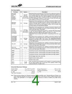
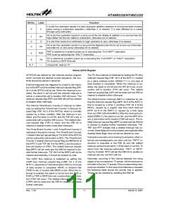
The system clock is derived from either a crystal or an
RC oscillator or an 32768Hz crystal. It is internally di-
vided into four non-overlapping clocks. One instruction
cycle consists of four system clock cycles. Instruction
fetching and execution are pipelined in such a way that a
fetch takes one instruction cycle while decoding and ex-
ecution takes the next instruction cycle. The pipelining
scheme makes it possible for each instruction to be ef-
fectively executed in a cycle. If an instruction changes
the value of the program counter, two cycles are re-
quired to complete the instruction.
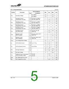
The program counter (PC) is 14 bits wide and it controls
the sequence in which the instructions stored in the pro-
gram ROM are executed. The contents of the PC can
specify a maximum of 16384´16 addresses. After ac-
cessing a program memory word to fetch an instruction
code, the value of the PC is incremented by 1. The PC
then points to the memory word containing the next in-
struction code. When executing a jump instruction, con-
ditional skip execution, loading a PCL register, a
subroutine call, an initial reset, an internal interrupt, an
external interrupt, or returning from a subroutine, the PC
T
1
T
2
T
3
T
4
T
1
T
2
T
3
T
4
T
1
T
2
T
3
T
4
S
y
s
t
e
m
C
l
o
c
k
O
S
C
2
(
R
C
o
n
l
y
)
P
C
P
C
+
1
P
C
+
2
P
C
F
e
t
c
h
I
N
S
T
(
P
C
)
E
x
e
c
u
t
e
I
N
S
T
(
P
C
-
1
)
F
e
t
c
h
I
N
S
T
(
P
C
+
1
)
E
x
e
c
u
t
e
I
N
S
T
(
P
C
)
F
e
t
c
h
I
N
S
T
(
P
C
+
2
)
E
x
e
c
u
t
e
I
N
S
T
(
P
C
+
1
)
Execution Flow
Program Counter
Mode
*13 *12 *11 *10 *9
*8
0
0
0
0
0
0
0
*7
0
0
0
0
0
0
0
*6
0
0
0
0
0
0
0
*5
0
0
0
0
0
0
0
*4
0
0
0
0
1
1
1
*3
0
0
1
1
0
0
1
*2
0
1
0
1
0
1
0
*1
0
0
0
0
0
0
0
*0
0
0
0
0
0
0
0
Initial Reset
External Interrupt
0
0
0
0
0
0
0
0
0
0
0
0
0
0
0
0
0
0
0
0
0
0
0
0
0
0
0
0
0
0
0
0
0
0
0
Timer/Event Counter 0 Overflow
Timer/Event Counter 1 Overflow
UART Bus Interrupt
I2C Bus Interrupt
Multi-function Interrupt
Skip
Program Counter + 2 (Within the current bank)
*13 *12 *11 *10 *9 *8 @7 @6 @5 @4 @3 @2 @1 @0
Loading PCL
Jump, Call Branch
BP.5 #12 #11 #10 #9 #8 #7 #6 #5 #4 #3 #2 #1 #0
S13 S12 S11 S10 S9 S8 S7 S6 S5 S4 S3 S2 S1 S0
Return from Subroutine
Program Counter
Note: *13~*0: Program counter bits
#12~#0: Instruction code bits
S13~S0: Stack register bits
@7~@0: PCL bits
1
3
1
2
8
7
0
P
r
o
g
r
a
m
C
o
u
n
t
e
r
B
P
.
5
B
a
n
k
P
o
i
n
t
e
r
(
B
P
)
Rev. 1.30
7
March 9, 2007

 HOLTEK [ HOLTEK SEMICONDUCTOR INC ]