HT46RU25/HT46CU25
manages the program transfer by loading the address
corresponding to each instruction.
bank has 8192´16 bit and is selected by setting the
bank pointer (BP.5; Bank0, BP=000XXXXXB; Bank1:
BP=001XXXXXB). The JMP and CALL instructions pro-
vide only 13 bits of address to allow branching within
any 8K program memory. When doing a JMP or CALL
instruction, the user must ensure that the bank pointer
bit (BP.5) is programmed so that the desire program
memory bank is addressed. If a return from a CALL in-
struction or interrupt is executed, the entire 14 bit pro-
gram counter is popped off the stack. Therefore,
manipulation of the BP.5 is not required for the RET or
RETI instructions.
The conditional skip is activated by instructions. Once
the condition is met, the next instruction, fetched during
the current instruction execution, is discarded and a
dummy cycle replaces it to get a proper instruction; oth-
erwise proceed to the next instruction.
The lower byte of the PC (PCL) is a readable and
writeable register (06H). Moving data into the PCL per-
forms a short jump. The destination is within 256 loca-
tions.
When a control transfer takes place, an additional
dummy cycle is required.
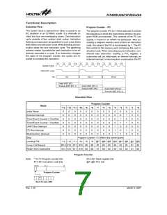
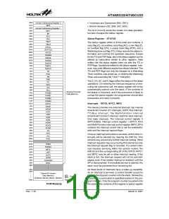
Certain locations in the ROM are reserved for special
usage:
·
Location 000H
Program Memory - EPROM
Location 000H is reserved for program initialization.
After a chip reset, the program always begins execu-
tion at this location.
The program memory (EPROM) is used to store the pro-
gram instructions, which are to be executed. It also con-
tains data, table, and interrupt entries, and is organized
into 16384´16 bits format which are addressed by the
program counter and table pointer. The ROM memory is
divided into two banks (Bank0 and Bank1). Each ROM
·
Location 004H
Location 004H is reserved for the external interrupt
service program. If the INT input pin is activated, and
the interrupt is enabled, and the stack is not full, the
program begins execution at location 004H.
0
0
0
0
0
0
0
4
8
H
H
H
D
e
v
i
c
e
I
n
i
t
i
a
l
i
z
a
t
i
o
n
P
r
o
g
r
a
m
·
·
·
Location 008H
E
x
t
e
r
n
a
l
I
n
t
e
r
r
u
p
t
S
u
b
r
o
u
t
i
n
e
Location 008H is reserved for the Timer/Event Coun-
ter 0 interrupt service program. If a timer interrupt re-
sults from a Timer/Event Counter 0 overflow, and if the
interrupt is enabled and the stack is not full, the pro-
gram begins execution at location 008H.
T
T
i
i
m
m
e
e
r
r
/
/
E
E
v
v
e
e
n
n
t
t
C
C
o
o
u
u
n
n
t
t
e
e
r
r
0
1
I
I
n
n
t
t
e
e
r
r
r
r
u
u
p
p
t
t
o
S
S
u
u
b
b
r
r
o
o
u
u
t
t
i
i
n
n
e
e
0
0
C
H
0
0
0
1
1
1
0
4
8
H
H
H
U
A
R
T
B
u
s
I
n
t
e
r
r
u
p
t
S
u
b
r
u
t
i
n
e
2
I
C
B
u
s
I
n
t
e
r
r
u
p
t
S
u
b
r
o
u
t
i
n
e
Location 00CH
P
r
o
g
r
a
m
M
e
m
o
r
y
Location 00CH is reserved for the Timer/Event Coun-
ter 1 interrupt service program. If a timer interrupt re-
sults from a Timer/Event Counter 1 overflow, and if the
interrupt is enabled and the stack is not full, the pro-
gram begins execution at location 00CH.
M
u
l
t
i
-
f
u
n
c
t
i
o
n
I
n
t
e
r
r
u
p
t
S
u
b
r
o
u
t
i
n
e
n
0
0
H
L
o
o
k
-
u
p
T
a
b
l
e
(
2
5
6
w
o
r
d
s
)
n
F
F
H
Location 010H
1
F
0
0
H
Location 010H is reserved for the UART Bus interrupt
service program. If the UART Bus interrupt resulting
from transmission flag or reception is completed, and
if the interrupt is enabled and the stack is not full, the
program begins execution at location 010H.
L
o
o
k
-
u
p
T
a
b
l
e
(
2
5
6
w
o
r
d
s
)
1
F
F
F
H
1
6
b
i
t
s
N
o
t
e
:
n
r
a
n
g
e
s
f
r
o
m
0
t
o
1
F
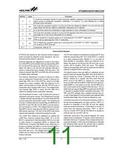
Program Memory
Table Location
Instruction
*13~*8
TBHP
*7
*6
*5
*4
*3
*2
*1
*0
TABRDC [m]
TABRDL [m]
@7
@7
@6
@6
@5
@5
@4
@4
@3
@3
@2
@2
@1
@1
@0
@0
111111
Table Location
TBHP: Table pointer higher-order bits
Note: *13~*0: Table location bits
@7~@0: Table pointer bits
Rev. 1.30
8
March 9, 2007

 HOLTEK [ HOLTEK SEMICONDUCTOR INC ]