HT46RU25/HT46CU25
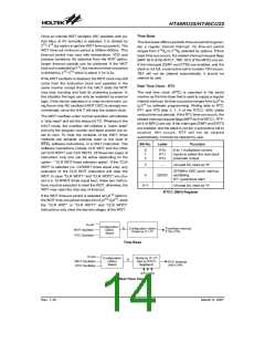
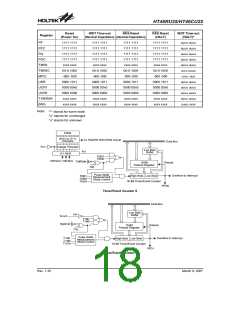
Time Base
Once an internal WDT oscillator (RC oscillator with pe-
riod 65ms at 5V normally) is selected, it is divided by
2
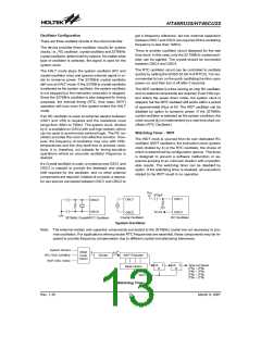
The time base offers a periodic time-out period to gener-
ate a regular internal interrupt. Its time-out period
ranges from 212/fS to 215/fS selected by options. If time
base time-out occurs, the related interrupt request flags
(MFF bit 6 of the INTC1, TBF; bit 5 of the MFIC) are set.
If the interrupts (EMFI and ETBI) are enabled, and the
stack is not full, a subroutine call to location 18H occurs.
TBF will not be cleared automatically, it should be
cleared by user.
12~215 (by option to get the WDT time-out period). The
WDT time-out minimum period is 300ms~600ms. This
time-out period may vary with temperature, VDD and
process variations. By selection from the WDT option,
longer time-out periods can be achieved. If the WDT
time-out is selected at 215, the maximum time-out period
is divided by 215~216 which is about 2.1s~4.3s.
If the WDT oscillator is disabled, the WDT clock may still
come from the instruction clock and operates in the
same manner except that in the HALT state the WDT
may stop counting and lose its protecting purpose. In
this situation the logic can only be restarted by external
logic. If the device operates in a noisy environment, us-
ing the on-chip RC oscillator (WDT OSC) is strongly rec-
ommended, since the HALT will stop the system clock.
Real Time Clock - RTC
The real time clock (RTC) is operated in the same
manner as the time base that is used to supply a regular
internal interrupt. Its time-out period ranges from fS/28 to
fS/215 by software programming. Writing data to RT2,
RT1 and RT0 (bits 2, 1, 0 of the RTCC; 09H) yields
various time-out periods. If the RTC time-out occurs, the
related interrupt request flags (MFF bit 6 of INTC1, RTF;
bit 6 of MFIC) are set. If the interrupts (EMFI and ERTI)
are enabled, and the stack is not full, a subroutine call to
location 18H occurs. RTF will not be cleared
automatically, it should be cleared by user.
The WDT overflow under normal operation will initialize
a ²chip reset² and set the status bit TO. Whereas in the
HALT mode, the overflow will initialize a ²warm reset²
and only the program counter and stack pointer are re-
set to zero. To clear the contents of the WDT, three
methods are adopted; external reset (a low level to
RES), software instructions, or a HALT instruction. The
software instructions include CLR WDT and the other
set CLR WDT1 and CLR WDT2. Of these two types of
instruction, only one can be active depending on the
option - ²CLR WDT times selection option². If the ²CLR
WDT² is selected (i.e. CLRWDT times equal one), any
execution of the CLR WDT instruction will clear the
WDT. In case ²CLR WDT1² and ²CLR WDT2² are cho-
sen (i.e. CLRWDT times equal two), these two instruc-
tions must be executed to clear the WDT, otherwise, the
WDT may reset the chip due of time-out.
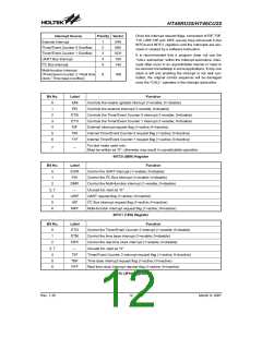
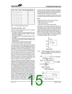
Bit No.
Label
Function
0
1
2
RT0
RT1
RT2
8 to 1 multiplexer control
inputs to select the real clock
prescaler output
3
¾
QOSC
¾
Unused bit, read as ²0²
32768Hz OSC quick start-up
oscillating
4
0/1: quick/slow start
5~7
Unused bit, read as ²0²
RTCC (09H) Register
If the WDT time-out period is selected at fs/212 (option),
the WDT time-out period ranges from fs/212~fs/213, since
the ²CLR WDT² or ²CLR WDT1² and ²CLR WDT2²
instructions only clear the last two stages of the WDT.
S
Y
S
C
o
n
f
i
g
u
r
a
t
i
o
n
f
S
C
o
n
f
i
g
u
r
a
t
i
o
n
O
p
t
i
o
n
T
i
m
e
B
a
s
e
I
n
t
e
r
r
u
p
t
O
p
t
i
o
n
W
D
T
T
O
O
s
s
c
c
i
i
l
l
l
l
a
a
t
t
o
r
r
1
2
1
5
1
2
1
5
D
i
v
i
d
e
b
y
2
~
2
2
/
f
S
~
2
/
f
S
S
e
l
e
c
t
R
C
o
Time Base
S
Y
S
8
D i v i d e b y 2 ~ 2
1
5
C
o
n
f
i
g
u
r
a
t
i
o
n
f
S
W
D
T
T
O
O
s
s
c
c
i
i
l
l
l
l
a
a
t
t
o
r
r
O
p
t
i
o
n
(
S
e
t
b
y
R
T
C
C
R
T
C
I
n
t
e
r
r
u
p
t
8
1
5
S
e
l
e
c
t
R
e
g
i
s
t
e
r
s
)
2
/
f
S
~
2
/
f
R
C
o
R
T
2
~
R
T
0
Real Time Clock
Rev. 1.30
14
March 9, 2007

 HOLTEK [ HOLTEK SEMICONDUCTOR INC ]