HT46RU25/HT46CU25
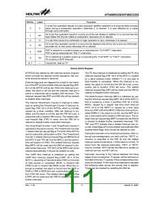
Oscillator Configuration
get a frequency reference, but two external capacitors
between OSC1 and OSC2 are required (If the oscillating
frequency is less than 1MHz).
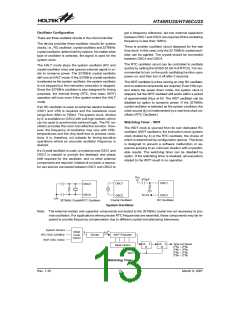
There are three oscillator circuits in the microcontroller.
The device provides three oscillator circuits for system
clocks, i.e., RC oscillator, crystal oscillator and 32768Hz
crystal oscillator, determined by options. No matter what
type of oscillator is selected, the signal is used for the
system clock.
There is another oscillator circuit designed for the real
time clock. In this case, only the 32.768kHz crystal oscil-
lator can be applied. The crystal should be connected
between OSC3 and OSC4.
The RTC oscillator circuit can be controlled to oscillate
quickly by setting the QOSC bit (bit 4 of RTCC). It is rec-
ommended to turn on the quick oscillating function upon
power on, and then turn it off after 2 seconds.
The HALT mode stops the system oscillator (RC and
crystal oscillator only) and ignores external signal in or-
der to conserve power. The 32768Hz crystal oscillator
still runs at HALT mode. If the 32768Hz crystal oscillator
is selected as the system oscillator, the system oscillator
is not stopped but the instruction execution is stopped.
Since the 32768Hz oscillator is also designed for timing
purposes, the internal timing (RTC, time base, WDT)
operation still runs even if the system enters the HALT
mode.
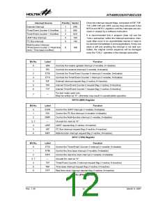
The WDT oscillator is a free running on-chip RC oscillator,
and no external components are required. Even if the sys-
tem enters the power down mode, the system clock is
stopped, but the WDT oscillator still works within a period
of approximately 65ms at 5V. The WDT oscillator can be
disabled by option to conserve power. If the 32768Hz
crystal oscillator is selected as the system oscillator, the
clock source (fS) is implemented by a real time clock os-
cillator (RTC Oscillator)
If an RC oscillator is used, an external resistor between
OSC1 and VSS is required and the resistance must
range from 30kW to 750kW. The system clock, divided
by 4, is available on OSC2 with pull-high resistor, which
can be used to synchronize external logic. The RC os-
cillator provides the most cost effective solution. How-
ever, the frequency of oscillation may vary with VDD,
temperatures and the chip itself due to process varia-
tions. It is, therefore, not suitable for timing sensitive
operations where an accurate oscillator frequency is
desired.
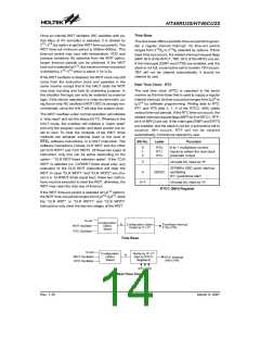
Watchdog Timer - WDT
The WDT clock is sourced from its own dedicated RC
oscillator (WDT oscillator), the instruction clock (system
clock divided by 4) or the RTC oscillator, the choice of
which is determined by configuration options. This timer
is designed to prevent a software malfunction or se-
quence jumping to an unknown location with unpredict-
able results. The watchdog timer can be disabled by
option. If the watchdog timer is disabled, all executions
related to the WDT result in no operation.
If a Crystal oscillator is used, a crystal across OSC1 and
OSC2 is needed to provide the feedback and phase
shift required for the oscillator, and no other external
components are required. Instead of a crystal, a resona-
tor can also be connected between OSC1 and OSC2 to
V
D
D
4
7
0
p
F
O
S
C
1
O
S
C
1
O
S
C
3
O
S
C
4
S
Y
S
O
S
C
2
O
S
C
2
C
r
y
s
t
a
l
O
s
c
i
l
l
a
t
o
r
R
C
O
s
c
i
l
l
a
t
o
r
3
2
7
6
8
H
z
C
r
y
s
t
a
l
/
R
T
C
O
s
c
i
l
l
a
t
o
r
System Oscillator
Note: The external resistor and capacitor components connected to the 32768Hz crystal are not necessary to pro-
vide oscillation. For applications where precise RTC frequencies are essential, these components may be re-
quired to provide frequency compensation due to different crystal manufacturing tolerances.
S
y
s
t
e
C
m
C
l
o
c
k
/
4
8
f
s
R
O
M
s
f / 2
R
T
C
O
S
3
2
7
6
8
H
H
z
z
D
i
v
i
d
e
r
W
D
T
P
r
e
s
c
a
l
e
r
C
o
d
e
O
p
t
i
o
n
W
D
T
O
S
C
1
2
k
T
i
m
e
-
o
u
t
R
e
s
e
t
C
K
T
C
K
T
M
a
s
k
O
p
t
i
o
n
1
1
1
1
5
4
3
2
1
1
1
1
6
5
4
3
2
/
f
S
S
S
S
~
~
~
~
2
2
2
2
/
/
/
/
f
f
f
f
S
S
S
S
R
R
2
2
2
/
/
/
f
f
f
W
D
T
C
l
e
a
r
Watchdog Timer
Rev. 1.30
13
March 9, 2007

 HOLTEK [ HOLTEK SEMICONDUCTOR INC ]