Preliminary
HT45R04/HT45R04E
quency may vary with VDD, temperatures and the chip
itself due to process variations. It is, therefore, not suit-
able for timing sensitive operations where an accurate
oscillator frequency is desired.
HALT mode, the overflow will initialize a ²warm reset²,
and only the Program Counter and SP are reset to zero.
To clear the WDT contents (including the WDT
prescaler), three methods are adopted; external reset (a
low level to RES), software instruction and a ²HALT² in-
struction. The software instructions include ²CLR WDT²
and the other set - ²CLR WDT1² and ²CLR WDT2². Of
these two types of instruction, only one can be active de-
pending on the option - ²CLR WDT times selection op-
tion². If the ²CLR WDT² is selected (i.e. CLRWDT times
equal one), any execution of the ²CLR WDT² instruction
will clear the WDT. In the case that ²CLR WDT1² and
²CLR WDT2² are chosen (i.e. CLRWDT times equal
two), these two instructions must be executed to clear
the WDT, otherwise, the WDT may reset the chip as a
result of time-out.
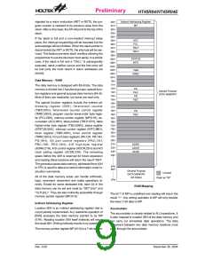
If the Crystal oscillator is used, a crystal across OSC1
and OSC2 is needed to provide the feedback and phase
shift required for the oscillator, and no other external
components are required. Instead of a crystal, a
resonator can also be connected between OSC1 and
OSC2 to get a frequency reference, but two external
capacitors in OSC1 and OSC2 are required (if the
oscillating frequency is less than 1MHz).
The WDT oscillator is a free running on-chip RC oscilla-
tor, and no external components are required. Even if
the system enters the power down mode, the system
clock is stopped, but the WDT oscillator still works with a
period of approximately 65ms at 5V. The WDT oscillator
can be disabled by options to conserve power.
Power Down Operation - HALT
The HALT mode is initialized by the ²HALT² instruction
and results in the following:
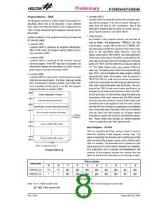
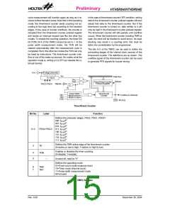
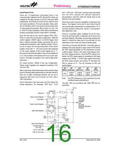
Watchdog Timer - WDT
The WDT clock source is implemented by a dedicated
RC oscillator (WDT oscillator) or instruction clock (sys-
tem clock divided by 4) determined by options. This
timer is designed to prevent a software malfunction or
sequence jumping to an unknown location with unpre-
dictable results. The watchdog timer can be disabled by
option. If the watchdog timer is disabled, all executions
related to the WDT result in no operation.
·
The system oscillator will be turned off but the WDT
oscillator keeps running (if the WDT oscillator is se-
lected).
·
·
The contents of the on-chip RAM and registers remain
unchanged.
WDT and WDT prescaler will be cleared and re-
counted again (if the WDT clock is from the WDT os-
cillator).
Once the internal WDT oscillator (RC oscillator with a
period of 65ms at 5V normally) is selected, it is divided by
216 to get the nominal time-out period of approximately
5.1s at 5V. This time-out period may vary with tempera-
ture, VDD and process variations. By invoking the WDT
prescaler, longer time-out periods can be realized. If the
WDT oscillator is disabled, the WDT clock may still
come from the instruction clock and operates in the
same manner except that in the HALT state the WDT
may stop counting and lose its protecting purpose. In
this situation the logic can only be restarted by external
logic.
·
·
All of the I/O ports maintain their original status.
The PDF flag is set and the TO flag is cleared.
The system can leave the HALT mode by means of an
external reset, an interrupt, an external falling edge sig-
nal on port A or a WDT overflow. An external reset
causes a device initialization and the WDT overflow per-
forms a ²warm reset². After the TO and PDF flags are
examined, the cause for a chip reset can be determined.
The PDF flag is cleared by a system power-up or exe-
cuting the ²CLR WDT² instruction and is set when exe-
cuting the ²HALT² instruction. The TO flag is set if the
WDT time-out occurs, and causes a wake-up that only
resets the Program Counter and SP, the other circuits
maintain their original status.
If the device operates in a noisy environment, using the
on-chip RC oscillator (WDT OSC) is strongly recom-
mended, since the HALT will stop the system clock.
The port A wake-up and interrupt methods can be con-
sidered as a continuation of normal execution. Each bit
in port A can be independently selected to wake up the
The WDT overflow under normal operation will initialize
a ²chip reset² and set the status bit ²TO². But in the
S
y
s
t
e
m
C
l
o
c
k
/
4
f
s
O
p
t
i
o
n
W
f
D T T i m e - o u t
5
s
~ f / 2
8
-
b
i
t
C
o
u
n
t
e
r
7
-
b
i
t
C
o
u
n
t
e
r
T
T
1
1
6
S
e
l
e
c
t
s
/
2
W
D
T
C
L
R
W
D
T
O
S
C
Watchdog Timer
Rev. 0.00
12
December 30, 2004

 HOLTEK [ HOLTEK SEMICONDUCTOR INC ]