Preliminary
HT45R04/HT45R04E
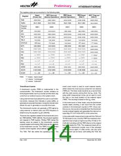
The registers state are summarized in the following table.
Reset
(Power On)
WDT time-out RES Reset
(Normal Operation) (Normal Operation)
RES Reset
(HALT)
WDT Time-out
(HALT)*
Register
TMR
xxxx xxxx
00-0 1000
uuuu uuuu
00-0 1000
uuuu uuuu
00-0 1000
uuuu uuuu
00-0 1000
uuuu uuuu
uu-u uuuu
TMRC
Program
Counter
000H
000H
000H
000H
000H
MP
-xxx xxxx
xxxx xxxx
xxxx xxxx
--xx xxxx
--00 xxxx
-000 0000
1111 1111
1111 1111
---- 1111
---- 1111
---- ---1
-uuu uuuu
uuuu uuuu
uuuu uuuu
--uu uuuu
--1u uuuu
-000 0000
1111 1111
1111 1111
---- 1111
---- 1111
---- ---1
-uuu uuuu
uuuu uuuu
uuuu uuuu
--uu uuuu
--uu uuuu
-000 0000
1111 1111
1111 1111
---- 1111
---- 1111
---- ---1
-uuu uuuu
uuuu uuuu
uuuu uuuu
--uu uuuu
--01 uuuu
-000 0000
1111 1111
1111 1111
---- 1111
---- 1111
---- ---1
-uuu uuuu
uuuu uuuu
uuuu uuuu
--uu uuuu
--11 uuuu
-uuu uuuu
uuuu uuuu
uuuu uuuu
---- uuuu
ACC
TBLP
TBLH
STATUS
INTC
PA
PAC
PB
PBC
PD
---- uuuu
---- ---u
PDC
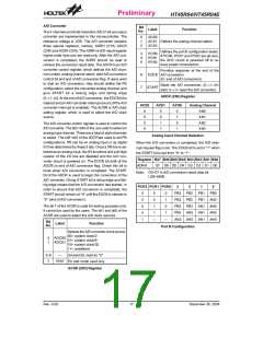
ADRH
ADCR
ACSR
---- ---1
---- ---1
---- ---1
---- ---1
---- ---u
xxxx xxxx
0100 0000
1--- --00
xxxx xxxx
0100 0000
1--- --00
xxxx xxxx
0100 0000
1--- --00
xxxx xxxx
0100 0000
1--- --00
uuuu uuuu
uuuu uuuu
u--- --uu
Note:
²*² means ²warm reset²
²u² means ²unchanged²
²x² means ²unknown²
Timer/Event Counter
event count mode is used to count external events,
which means the clock source comes from an external
(TMR) pin. The timer mode functions as a normal timer
with the clock source coming from the fINT clock. The
pulse width measurement mode can be used to count
the high or low level duration of the external signal
(TMR). The counting is based on the fINT clock.
A timer/event counter (TMR) is implemented in the
microcontroller. The timer/event counter contains an
8-bit programmable count-up counter and the clock may
come from an external source or the system clock.
Using external clock input allows the user to count exter-
nal events, measure time internals or pulse widths, or
generate an accurate time base. Using the internal clock
allows the user to generate an accurate time base.
In the event count or timer mode, once the timer/event
counter starts counting, it will count from the current
contents in the timer/event counter to FFH. Once over-
flow occurs, the counter is reloaded from the timer/event
counter preload register and generates the interrupt re-
quest flag (TF; bit 5 of the INTC) at the same time.
The timer/event counter can generate a PFD signal by
using external or internal clock and PFD frequency is
determine by the equation fINT/[2´(256-N)].
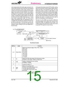
There are two registers related to the timer/event coun-
ter; TMR ([0DH]), TMRC ([0EH]). Two physical registers
are mapped to TMR location. Writing TMR makes the
starting value be placed in the timer/event counter
preload register and reading TMR retrieves the contents
of the timer/event counter. The TMRC is a timer/event
counter control register, which defines some options.
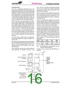
In the pulse width measurement mode with the TON and
TE bits equal to one, once the TMR has received a tran-
sient from low to high (or high to low if the TE bits is ²0²)
it will start counting until the TMR returns to the original
level and resets the TON. The measured result will re-
main in the timer/event counter even if the activated
transient occurs again. In other words, only one cycle
measurement can be done. Until setting the TON, the
The TM0, TM1 bits define the operating mode. The
Rev. 0.00
14
December 30, 2004

 HOLTEK [ HOLTEK SEMICONDUCTOR INC ]