Preliminary
HT45R04/HT45R04E
Bit No.
Label
EMI
EEI
ETI
Function
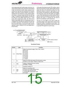
Controls the master (global) interrupt (1= enable; 0= disable)
Controls the external interrupt (1= enable; 0= disable)
0
1
2
3
4
5
6
7
Controls the timer/event counter interrupt (1= enable; 0= disable)
Controls the A/D converter interrupt (1= enable; 0= disable)
External interrupt request flag (1= active; 0= inactive)
Internal timer/event counter request flag (1= active; 0= inactive)
A/D converter request flag (1= active; 0= inactive)
Unused bit, read as ²0²
EADI
EIF
TF
ADF
¾
INTC (0BH) Register
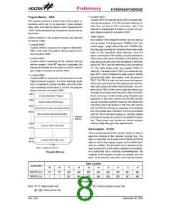
The internal timer/event counter interrupt is initialized by
setting the timer/event counter interrupt request flag
(TF; bit 5 of the INTC), caused by a timer overflow.
When the interrupt is enabled, the stack is not full and
the TF bit is set, a subroutine call to location 08H will oc-
cur. The related interrupt request flag (TF) will be reset
and the EMI bit cleared to disable further interrupts.
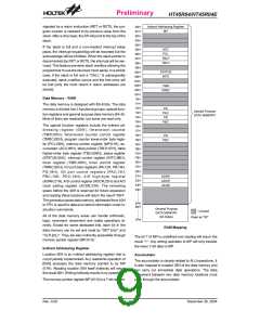
isters (INTC) which is located at 0BH in the data
memory. EMI, EEI, ETI, EADI and are used to control
the enabling/disabling of interrupts. These bits prevent
the requested interrupts from being serviced. Once the
interrupt request flags (TF, EIF, ADF) are set, they will
remain in the INTC register until the interrupts are ser-
viced or cleared by a software instruction.
The A/D converter end-of-conversion interrupt is initial-
ized by setting the A/D end-of-conversion interrupt re-
quest flag (bit 6 of the INTC), caused by an end of A/D
conversion. When the interrupt is enabled, the stack is
not full and the end of A/D conversion interrupt request
flag is set, a subroutine call to location 00CH will occur.
The related interrupt request flag will be reset and the
EMI bit cleared to disable further interrupts.
It is recommended that a program does not use the
²CALL subroutine² within the interrupt subroutine. Inter-
rupts often occur in an unpredictable manner or need to
be serviced immediately in some applications. If only
one stack is left and enabling the interrupt is not well
controlled, the original control sequence will be dam-
aged once the ²CALL² operates in the interrupt subrou-
tine.
During the execution of an interrupt subroutine, other in-
terrupt acknowledge are held until the ²RETI²
instruction is executed or the EMI bit and the related in-
terrupt control bit are set to 1 (if the stack is not full). To
return from the interrupt subroutine, ²RET² or ²RETI²
may be invoked. RETI will set the EMI bit to enable an
interrupt service, but RET will not.
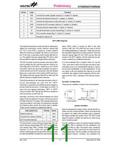
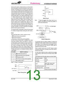
Oscillator Configuration
There are two oscillator circuits in the microcontroller.
V
D
D
O
S
C
1
O
S
C
1
Interrupts, occurring in the interval between the rising
edges of two consecutive T2 pulses, will be serviced on
the latter of the two T2 pulses, if the corresponding inter-
rupts are enabled. In the case of simultaneous requests
the following table shows the priority that is applied.
These can be masked by resetting the EMI bit.
S
Y
S
O
S
C
2
O
S
C
2
N
M
O
S
O
p
e
n
D
r
a
i
n
C
r
y
s
t
a
l
O
s
c
i
l
l
a
t
o
r
R
C
O
s
c
i
l
l
a
t
o
r
System Oscillator
Both are designed for system clocks, namely the RC os-
cillator and the Crystal oscillator, which are determined
by options. No matter what oscillator type is selected,
the signal provides the system clock. The HALT mode
stops the system oscillator and ignores an external sig-
nal to conserve power.
Interrupt Source
External Interrupt
Priority Vector
1
2
3
04H
08H
0CH
Timer/Event Counter Overflow
A/D Converter Interrupt
The timer/event counter interrupt request flag (TF), ex-
ternal interrupt request flags (EIF), A/D converter inter-
rupt request flag (ADF), enable timer/event counter
interrupt bit (ETI), enable A/D converter interrupt
(EADI), enable external interrupt (EEI) and enable mas-
ter interrupt bit(EMI) constitute the interrupt control reg-
If an RC oscillator is used, an external resistor between
OSC1 and VSS is required and the resistance must
range from 24kW to 1MW. The system clock, divided by
4, is available on OSC2, which can be used to synchro-
nize external logic. The RC oscillator provides the most
cost effective solution. However, the oscillation fre-
Rev. 0.00
11
December 30, 2004

 HOLTEK [ HOLTEK SEMICONDUCTOR INC ]