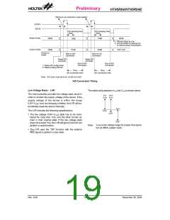
Preliminary
HT45R04/HT45R04E
cycle measurement will function again as long as it re-
ceives further transient pulse. Note that in this operating
mode, the timer/event counter starts counting not ac-
cording to the logic level but according to the transient
edges. In the case of counter overflows, the counter is
reloaded from the timer/event counter preload register
and issues an interrupt request just like the other two
modes. To enable the counting operation, the timer ON
bit (TON; bit 4 of the TMRC) should be set to 1. In the
pulse width measurement mode, the TON will be
cleared automatically after the measurement cycle is
completed. But in the other two modes the TON can only
be reset by instructions. The timer/event counter over-
flow is one of the wake-up sources. No matter what the
operation mode is, writing a 0 to ETI can disable the in-
terrupt service.
In the case of timer/event counter OFF condition, writing
data to the timer/event counter preload register will also
reload that data to the timer/event counter. But if the
timer/event counter is turned on, data written to it will
only be kept in the timer/event counter preload register.
The timer/event counter will still operate until overflow
occurs. When the timer/event counter (reading TMR) is
read, the clock will be blocked to avoid errors. As clock
blocking may result in a counting error, this must be
taken into consideration by the programmer.
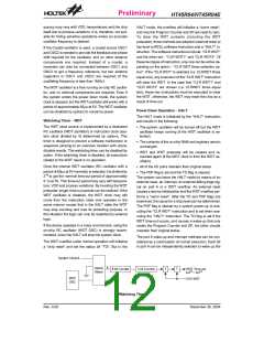
The bits 0~2 of the TMRC can be used to define the
pre-scaling stages of the internal clock sources of the
timer/event counter. The definitions are as shown. The
overflow signal of the timer/event counter can be used
to generate PFD signals for buzzer driving.
f
S Y S
8
-
s
t
a
g
e
p
r
e
s
c
a
l
e
r
f
I N T
D
a
t
a
B
u
s
8
-
1
M
U
X
T
M
1
R
e
l
o
a
d
T
i
m
e
r
/
E
v
e
n
t
C
o
u
n
t
e
r
T
M
0
P
r
e
l
o
a
d
R
e
g
i
s
t
e
r
P
S
C
2
~
P
S
C
0
T
M
R
T
E
P
u
l
s
e
W
i
d
t
h
T
i
m
e
r
/
E
v
e
n
t
T
M
1
O
v
e
r
f
l
o
w
t
o
I
n
t
e
r
r
u
p
t
M
e
a
s
u
r
e
m
e
n
t
C
o
u
n
t
e
r
T
M
0
M
o
d
e
C
o
n
t
r
o
l
T
O
N
1
/
2
P
F
D
Timer/Event Counter
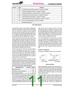
Bit No.
Label
Function
Defines the prescaler stages, PSC2, PSC1, PSC0=
000: fSYS/20
001: fSYS/21
010: fSYS/22
0~2
PSC0~PSC2 011: fSYS/23
100: fSYS/24
101: fSYS/25
110: fSYS/26
111: fSYS/27
Defines the TMR active edge of the timer/event counter
(0=active on low to high; 1=active on high to low)
3
TE
Enables or disables the timer counting
(0=disable; 1=enable)
4
5
TON
¾
Unused bit, read as ²0²
Defines the operating mode
01=Event count mode (external clock)
10=Timer mode (internal clock)
11=Pulse width measurement mode
00=Unused
6
7
TM0
TM1
TMRC Register
Rev. 0.00
15
December 30, 2004

 HOLTEK [ HOLTEK SEMICONDUCTOR INC ]