Preliminary
HT45R04/HT45R04E
Interrupt
Arithmetic and Logic Unit - ALU
The microcontroller provides an external interrupts, an
internal timer/event counter overflow interrupt, and an
A/D converter end-of-conversion interrupt. The interrupt
control registers (INTC;0BH ) contains the interrupt con-
trol bits to set the enable/disable and the interrupt re-
quest flags.
This circuit performs 8-bit arithmetic and logic opera-
tions. The ALU provides the following functions:
·
·
·
·
·
Arithmetic operations (ADD, ADC, SUB, SBC, DAA)
Logic operations (AND, OR, XOR, CPL)
Rotation (RL, RR, RLC, RRC)
Increment and Decrement (INC, DEC)
Branch decision (SZ, SNZ, SIZ, SDZ)
Once an interrupt subroutine is serviced, all the other in-
terrupts will be blocked (by clearing the EMI bit). This
scheme may prevent any further interrupt nesting. Other
interrupt requests may occur during this interval but only
the interrupt request flag is recorded. If a certain inter-
rupt requires servicing within the service routine, the
EMI bit and the corresponding bit of the INTC may be
set to allow interrupt nesting. If the stack is full, the inter-
rupt request will not be acknowledged, even if the re-
lated interrupt is enabled, until the SP is decremented. If
immediate service is desired, the stack must be pre-
vented from becoming full.
The ALU not only saves the results of a data operation
but also changes the status register.
Status Register - STATUS
This 8-bit register (0AH) contains the zero flag (Z), carry
flag (C), auxiliary carry flag (AC), overflow flag (OV),
power down flag (PDF), and watchdog time-out flag
(TO). It also records the status information and controls
the operation sequence.
With the exception of the TO and PDF flags, bits in the
status register can be altered by instructions like most
other registers. Any data written into the status register
will not change the TO or PDF flag. In addition, opera-
tions related to the status register may give different re-
sults from those intended. The TO flag can be affected
only by a system power-up, a WDT time-out or execut-
ing the ²CLR WDT² or ²HALT² instruction. The PDF flag
can be affected only by executing the ²HALT² or ²CLR
WDT² instruction or a system power-up.
All these kinds of interrupts have a wake-up capability.
As an interrupt is serviced, a control transfer occurs by
pushing the program counter onto the stack, followed by
a branch to a subroutine at specified location in the pro-
gram memory. Only the program counter is pushed onto
the stack. If the contents of the register or status register
(STATUS) are altered by the interrupt service program
which corrupts the desired control sequence, the con-
tents should be saved in advance.
External interrupts are triggered by a high to low transi-
tion of the INT and the related interrupt request flag (EIF;
bit 4 of the INTC) will be set. When the interrupt is en-
abled, the stack is not full and the external interrupt is
active, a subroutine call to location 04H will occur. The
interrupt request flag (EIF) and EMI bits will be cleared
to disable other interrupts.
The Z, OV, AC and C flags generally reflect the status of
the latest operations.
In addition, on entering the interrupt sequence or exe-
cuting a subroutine call, the status register will not be
automatically pushed onto the stack. If the contents of
the status are important and if the subroutine can cor-
rupt the status register, precautions must be taken to
save it properly.
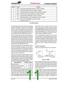
Bit No.
Label
Function
C is set if an operation results in a carry during an addition operation or if a borrow does not
take place during a subtraction operation, otherwise C is cleared. C is also affected by a rotate
through carry instruction.
0
C
AC is set if an operation results in a carry out of the low nibbles in addition or no borrow from
the high nibble into the low nibble in subtraction, otherwise AC is cleared.
1
2
3
AC
Z
Z is set if the result of an arithmetic or logic operation is zero, otherwise Z is cleared.
OV is set if an operation results in a carry into the highest-order bit but not a carry out of the
highest-order bit, or vice versa; otherwise OV is cleared.
OV
PDF is cleared by a system power-up or executing the ²CLR WDT² instruction. PDF is set by
executing the ²HALT² instruction.
4
5
PDF
TO
TO is cleared by a system power-up or executing the ²CLR WDT² or ²HALT² instruction. TO is
set by a WDT time-out.
6
7
¾
¾
Unused bit, read as ²0²
Unused bit, read as ²0²
Status (0AH) Register
Rev. 0.00
10
December 30, 2004

 HOLTEK [ HOLTEK SEMICONDUCTOR INC ]