Preliminary
HT45R04/HT45R04E
Functional Description
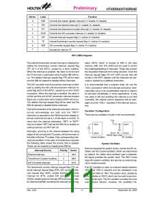
Execution Flow
incremented by one. The program counter then points to
the memory word containing the next instruction code.
The system clock for the microcontroller is derived from
either a crystal or an RC oscillator. The system clock is
internally divided into four non-overlapping clocks. One
instruction cycle consists of four system clock cycles.
When executing a jump instruction, conditional skip ex-
ecution, loading PCL register, subroutine call, initial re-
set, internal interrupt, external interrupt or return from
subroutine, the PC manages the program transfer by
loading the address corresponding to each instruction.
Instruction fetching and execution are pipelined in such
a way that a fetch takes an instruction cycle while de-
coding and execution takes the next instruction cycle.
However, the pipelining scheme allows each instruction
to be effectively executed in a cycle. If an instruction
changes the program counter, two cycles are required to
complete the instruction.
The conditional skip is activated by instructions. Once
the condition is met, the next instruction, fetched during
the current instruction execution, is discarded and a
dummy cycle replaces it to get the proper instruction.
Otherwise proceed with the next instruction.
The lower byte of the program counter (PCL) is a read-
able and writable register (06H). Moving data into the
PCL performs a short jump. The destination will be
within 256 locations.
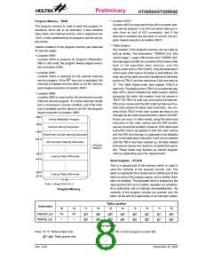
Program Counter - PC
The program counter (PC) controls the sequence in
which the instructions stored in program ROM are exe-
cuted and its contents specify full range of program
memory.
When a control transfer takes place, an additional
dummy cycle is required.
After accessing a program memory word to fetch an in-
struction code, the contents of the program counter are
T
1
T
2
T
3
T
4
T
1
T
2
T
3
T
4
T
1
T
2
T
3
T
4
S
y
s
t
e
m
C
l
o
c
k
O
S
C
2
(
R
C
o
n
l
y
)
P
C
P
C
+
1
P
C
+
2
P
C
F
e
t
c
h
I
N
S
T
(
P
C
)
E
x
e
c
u
t
e
I
N
S
T
(
P
C
-
1
)
F
e
t
c
h
I
N
S
T
(
P
C
+
1
)
E
x
e
c
u
t
e
I
N
S
T
(
P
C
)
F
e
t
c
h
I
N
S
T
(
P
C
+
2
)
E
x
e
c
u
t
e
I
N
S
T
(
P
C
+
1
)
Execution Flow
Program Counter
Mode
*9
0
*8
0
*7
0
*6
0
*5
0
*4
0
*3
0
*2
0
*1
0
*0
0
Initial Reset
External Interrupt
0
0
0
0
0
0
0
1
0
0
Timer/Event Counter Overflow
A/D Interrupt
0
0
0
0
0
0
1
0
0
0
0
0
0
0
0
0
1
1
0
0
Skip
Program Counter+2
Loading PCL
*9
*8
@7
#7
@6
#6
@5
#5
@4
#4
@3
#3
@2
#2
@1
#1
@0
#0
Jump, Call Branch
Return from Subroutine
#9
#8
S8
S9
S7
S6
S5
S4
S3
S2
S1
S0
Program Counter
Note: *9~*0: Program Counter bits
#9~#0: Instruction code bits
S9~S0: Stack register bits
@7~@0: PCL bits
Rev. 0.00
7
December 30, 2004

 HOLTEK [ HOLTEK SEMICONDUCTOR INC ]