FT2232C Dual USB UART / FIFO I.C.
9.6 Multi-Protocol Synchronous Serial Engine (MPSSE) Mode Signal Descriptions and
Interface Configurations
MPSSE Mode is designed to allow the FT2232C to interface efficiently with synchronous serial protocols such
as JTAG and SPI Bus. It can also be used to program SRAM based FPGA’s over USB. The MPSSE interface is
designed to be flexible so that it can be configured to allow any synchronous serial protocol (industry standard or
proprietary) to be interfaced to the FT2232C. MPSSE is available on channel A only.
MPSSE is fully configurable, and is programmed by sending commands down the data pipe. These can be sent
individually, or more efficiently in packets. MPSSE is capable of a maximum sustained data rate of 5.6 Mega bits / s.
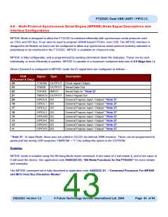
When Channel A is configured in MPSSE mode the IO signal lines are configured as follows :-
Pin#
Signal
Type
Description
(Channel A Only)
24
23
22
21
20
19
17
TCK/SK OUTPUT Clock signal Output
TDI/D0 OUTPUT Serial Data Out
TDO/DI INPUT Serial Data In **Note 27
TMS/CS OUTPUT Select Signal Out
GPIOL0 I/O
GPIOL1 I/O
GPIOL2 I/O
GPIOL3 I/O
GPIOH0 I/O
GPIOH1 I/O
GPIOH2 I/O
GPIOH3 I/O
General Pupose input / Output **Note 27
General Pupose input / Output **Note 27
General Pupose input / Output **Note 27
General Pupose input / Output **Note 27
General Pupose input / Output **Note 27
General Pupose input / Output **Note 27
General Pupose input / Output **Note 27
General Pupose input / Output **Note 27
16
15
13
12
11
**Note 27 : In Input Mode, these pins are pulled to VCCIO via internal 200K resistors. These can be programmed to
gently pull low during USB suspend ( PWREN# = “1” ) by setting this option in the EEPROM.
Enabling
MPSSE mode is enabled using Set Bit Bang Mode driver command. A hex value of 2 will enable it, and a hex value of
0 will reset the device. See application note AN2232C-02, “Bit Mode Functions for the FT2232C” for more details
and examples.
The MPSSE command set is fully described in application note AN2232C-01 - “Command Processor For MPSSE
and MCU Host Bus Emulation Modes”.
DS2232C Version 1.2
© Future Technology Devices International Ltd. 2004
Page 43 of 54

 FTDI [ FUTURE TECHNOLOGY DEVICES INTERNATIONAL LTD. ]