FT2232C Dual USB UART / FIFO I.C.
9.7 MCU Host Bus Emulation Mode Signal Descriptions and Interface Configuration
MCU host bus emulation mode uses both of the FT2232C’s A and B channel interfaces to make the chip emulate a
standard 8048 / 8051 MCU host bus. This allows peripheral devices for these MCU families to be directly connected to
USB via the FT2232C.
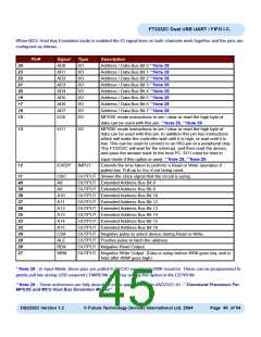
The lower 8 bits (AD7 to AD0) is a multiplexed Address / Data bus. A8 to A15 provide upper (extended) addresses.
There are 4 basic operations :-
1) Read (does not change A15 to A8)
2) Read Extended (changes A15 to A8)
3) Write (does not change A15 to A8)
4) Write Extended (changes A15 to A8)
Enabling
MCU Host Bus Emulation mode is enabled using Set Bit Bang Mode driver command. A hex value of 8 will enable
it, and a hex value of 0 will reset the device. See application note AN2232C-02, “Bit Mode Functions for the
FT2232C” for more details and examples.
The MCU Host Bus Emulation Mode command set is fully described in application note AN2232C-01 - “Command
Processor For MPSSE and MCU Host Bus Emulation Modes”.
DS2232C Version 1.2
© Future Technology Devices International Ltd. 2004
Page 44 of 54

 FTDI [ FUTURE TECHNOLOGY DEVICES INTERNATIONAL LTD. ]