FT2232C Dual USB UART / FIFO I.C.
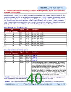
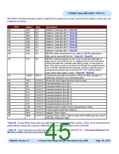
the main Channel mode is 245 FIFO, CPU FIFO interface, or Fast Opto-Isolated Serial Mode. Bit-Bang mode is not
available on Channel B when Fast Opto-Isolated Serial Mode is enabled.
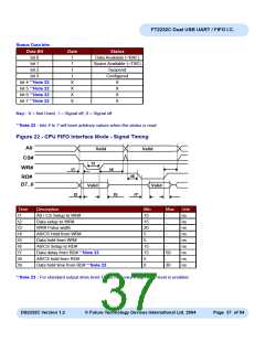
**Note 26 : The Bit-Bang Mode (synchronous and asynchronous) WR# and RD# strobes are on these pins when the
main Channel mode is set to 232 UART Mode.
Enhanced Asynchronous Bit-Bang Mode
Enhanced Asynchronous Bit-Bang mode is the same as BM-style Bit-Bang mode, except that the internal RD# and
WR# strobes are now brought out of the device to allow external logic to be clocked by accesses to the bit-bang IO
bus.
On either or both channels any data written to the device in the normal manner will be self clocked onto the data pins
(those which have been configured as outputs). Each pin can be independently set as an input or an output. The rate
that the data is clocked out at is controlled by the baud rate generator.
For the data to change there has to be new data written, and the baud rate clock has to tick. If no new data is written
to the channel, the pins will hold the last value written.
To allow time for the data to be setup and held around the WR# strobe, the baud rate should be less than 1
MegaBaud.
See the application note AN232B-01, “FT232BM/FT245BM Bit Bang Mode” for more details and a sample
application.
Enabling
Asynchronous Bit-Bang mode is enabled using Set Bit Bang Mode driver command. A hex value of 1 will enable it, and
a hex value of 0 will reset the device. See application note AN2232C-02, “Bit Mode Functions for the FT2232C” for
more details and examples of this.
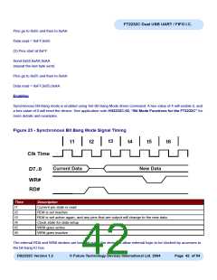
Synchronous Bit-Bang Mode
With Synchronous Bit-Bang mode data will only be sent out by the FT2232C if there is space in the device for data to
be read from the pins. This Synchronous Bit-Bang mode will read the data bus pins first, before it sends out the byte
that has just been transmitted. It is therefore 1 byte behind the output, and so to read the inputs for the byte that you
have just sent, another byte must be sent.
For example :-
(1) Pins start at 0xFF
Send 0x55,0xAA
DS2232C Version 1.2
© Future Technology Devices International Ltd. 2004
Page 41 of 54

 FTDI [ FUTURE TECHNOLOGY DEVICES INTERNATIONAL LTD. ]