FT2232C Dual USB UART / FIFO I.C.
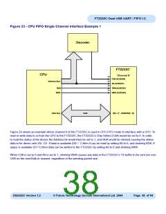
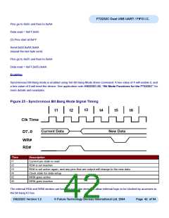
Figure 23 - CPU FIFO Single Channel Interface Example 1
Decoder
FT2232C
CPU
Channel A
15
13
12
11
CS# (ACBUS0)
Address Bus
A0 (ACBUS1)
RD# (ACBUS2)
WR# (ACBUS3)
RD#
WR#
Data Bus
Data
D[0...7] (ADBUS[0...7])
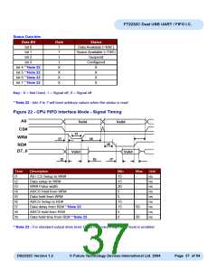
Figure 23 shows an example where channel A of the FT2232C is used in CPU FIFO mode to interface with a CPU. To
read or write data to or from the CPU to the FT2232C, the FT2232C’s Chip Select (CS#) would be set to 0. In order
to read the status of the device the Address bit would then be set to 1, and RD# would be strobed causing the status
data to be driven onto D0...D7. If data is available (D0 = 1) then it can be read by setting A0 to 0, and strobing RD#. If
space is available (D1=1) then data can be written to the FT2232C by setting A0 to 0 and strobing WR#.
When CS# is set to 0 and A0 is set to 1, strobing WR# causes any data in the FT2232C’s TX buffer to be sent out over
USB on the next Bulk-In request, regardless of the pending packet size.
DS2232C Version 1.2
© Future Technology Devices International Ltd. 2004
Page 38 of 54

 FTDI [ FUTURE TECHNOLOGY DEVICES INTERNATIONAL LTD. ]