FT2232C Dual USB UART / FIFO I.C.
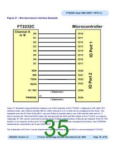
Figure 21 - Microprocessor Interface Example
FT2232C
Microcontroller
Channel A
D0
IO10
IO11
IO12
IO13
IO14
IO15
IO16
IO17
or B
D1
D2
D3
D4
D5
D6
D7
RD#
WR
IO20
IO21
IO22
IO23
TXE#
RXF#
SI / WU
IO24
IO25
( Optional )
41
PWREN#
( Optional )
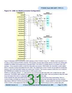
Figure 21 illustrates a typical interface between one of the channels of the FT2232C, configured in 245-style FIFO
interface mode, and a MicroController (MCU). Either channel A or B, or both can be configured in this mode. This
examples uses two IO Ports of the MCU, one port (8 bits) to transfer data to one of the and the other port (4 / 5
bits) to monitor the TXE# and RXF# status bits and generate the RD# and WR strobes to the FT2232C as required.
Optionally, SI / WU can be connected to another IO pin if either of the functions of this pin are required. If the SI / WU
function is not required, tie this pin to VCCIO. If the MCU is handling power management functions, then PWREN#
should also be connected to an IO pin of the MCU.
The 8 data bits on IO Port 1 can be shared with other peripherals when the MCU is not accessing the FT2232C.
DS2232C Version 1.2
© Future Technology Devices International Ltd. 2004
Page 35 of 54

 FTDI [ FUTURE TECHNOLOGY DEVICES INTERNATIONAL LTD. ]