FT2232C Dual USB UART / FIFO I.C.
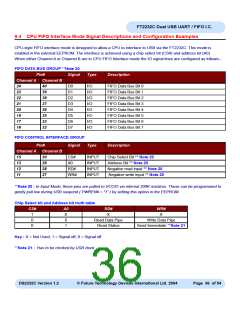
9.4 CPU FIFO Interface Mode Signal Descriptions and Configuration Examples
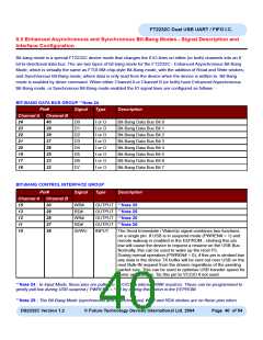
CPU-style FIFO interface mode is designed to allow a CPU to interface to USB via the FT2232C. This mode is
enabled in the external EEPROM. The interface is achieved using a chip select bit (CS#) and address bit (A0).
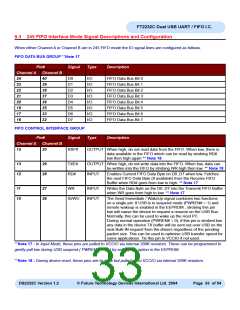
When either Channel A or Channel B are in CPU FIFO Interface mode the IO signal lines are configured as follows:-
FIFO DATA BUS GROUP **Note 20
Pin#
Signal
Type
Description
Channel A Channel B
24
23
22
21
20
19
17
16
40
39
38
37
36
35
33
32
D0
D1
D2
D3
D4
D5
D6
D7
I/O
I/O
I/O
I/O
I/O
I/O
I/O
I/O
FIFO Data Bus Bit 0
FIFO Data Bus Bit 1
FIFO Data Bus Bit 2
FIFO Data Bus Bit 3
FIFO Data Bus Bit 4
FIFO Data Bus Bit 5
FIFO Data Bus Bit 6
FIFO Data Bus Bit 7
FIFO CONTROL INTERFACE GROUP
Pin#
Signal
Type
Description
Channel A Channel B
15
13
12
11
30
29
28
27
CS#
A0
INPUT
INPUT
INPUT
INPUT
Chip Select Bit ** Note 20
Address Bit ** Note 20
RD#
WR#
Negative read input ** Note 20
Negative write input ** Note 20
**Note 20 : In Input Mode, these pins are pulled to VCCIO via internal 200K resistors. These can be programmed to
gently pull low during USB suspend ( PWREN# = “1” ) by setting this option in the EEPROM.
Chip Select bit and Address bit truth table
CS#
A0
X
RD#
X
WR#
X
1
0
0
0
Read Data Pipe
Read Status
Write Data Pipe
Send Immediate **Note 21
1
Key : X = Not Used; 1 = Signal off; 0 = Signal off
**Note 21 : Has to be clocked by USB clock.
DS2232C Version 1.2
© Future Technology Devices International Ltd. 2004
Page 36 of 54

 FTDI [ FUTURE TECHNOLOGY DEVICES INTERNATIONAL LTD. ]