FT2232C Dual USB UART / FIFO I.C.
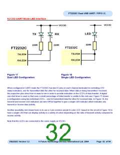
9.2 232 UART Mode LED Interface
VCCIO
VCCIO
LED
TX
RX
220R
220R
220R
FT2232C
FT2232C
TXLED#
RXLED#
TXLED#
RXLED#
Figure 17
Dual LED Configuration
Figure 18
Single LED Configuration
When configured in UART mode the FT2232C has two IO pins on each channel dedicated to controlling LED
status indicators, one for transmitted data the other for received data. When data is being transmitted / received
the respective pins drive from tri-state to low in order to provide indication on the LED’s of data transfer. A digital
one-shot timer is used so that even a small percentage of data transfer is visible to the end user. Figure 17 shows
a configuration using two individual LED’s – one for transmitted data the other for received data. In Figure 18, the
transmit and receive LED indicators are wire-OR’ed together to give a single LED indicator which indicates any
transmit or receive data activity.
Another possibility (not shown here) is to use a 3 pin common anode tri-color LED based on the circuit in Figure 18 to
have a single LED that can display activity in a variety of colors depending on the ratio of transmit activity compared to
receive activity.
Note that the LED’s are connected to the same supply as VCCIO.
DS2232C Version 1.2
© Future Technology Devices International Ltd. 2004
Page 32 of 54

 FTDI [ FUTURE TECHNOLOGY DEVICES INTERNATIONAL LTD. ]