Clock Generator Module (CGM)
is one-half of the base clock frequency, is one-fourth the frequency of the selected
clock (CGMXCLK or CGMVCLK).
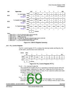
The BCS bit in the PLL control register (PCTL) selects which clock drives
CGMOUT. The VCO clock cannot be selected as the base clock source if the PLL
is not turned on. The PLL cannot be turned off if the VCO clock is selected. The
PLL cannot be turned on or off simultaneously with the selection or deselection of
the VCO clock. The VCO clock also cannot be selected as the base clock source
if the factor L is programmed to a 0. This value would set up a condition
inconsistent with the operation of the PLL, so that the PLL would be disabled and
the crystal clock would be forced as the source of the base clock.
4.3.4 CGM External Connections
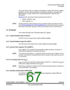
In its typical configuration, the CGM requires seven external components. Five of
these are for the crystal oscillator and two are for the PLL.
The crystal oscillator is normally connected in a Pierce oscillator configuration, as
shown in Figure 4-3. Figure 4-3 shows only the logical representation of the
internal components and may not represent actual circuitry.
SIMOSCEN
CGMXCLK
OSC1
OSC2
RS*
VSS
CGMXFC
CF
VDDA
VDD
CBYP
RB
X1
*RS can be 0 (shorted) when used with
higher frequency crystals. Refer to
manufacturer’s data.
C1
C2
Figure 4-3. CGM External Connections
The oscillator configuration uses five components:
1. Crystal, X1
2. Fixed capacitor, C1
3. Tuning capacitor, C2 (can also be a fixed capacitor)
4. Feedback resistor, RB
5. Series resistor, RS (optional)
Data Sheet
66
MC68HC908MR32 • MC68HC908MR16 — Rev. 6.0
Clock Generator Module (CGM) MOTOROLA

 FREESCALE [ Freescale ]