Clock Generator Module (CGM)
4.3.2.4 Programming the PLL
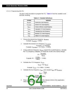
Use this 9-step procedure to program the PLL. Table 4-1 lists the variables used
and their meaning.
Table 4-1. Variable Definitions
Definition
Variable
fBUSDES
Desired bus clock frequency
Desired VCO clock frequency
Chosen reference crystal frequency
Calculated VCO clock frequency
Calculated bus clock frequency
Nominal VCO center frequency
Shifted FCO center frequency
fVCLKDES
fRCLK
fVCLK
fBUS
fNOM
fVRS
1. Choose the desired bus frequency, fBUSDES
Example: fBUSDES = 8 MHz
.
2. Calculate the desired VCO frequency, fVCLKDES
VCLKDES = 4 x fBUSDES
Example: fVCLKDES = 4 x 8 MHz = 32 MHz
.
f
3. Using a reference frequency, fRCLK, equal to the crystal frequency, calculate
the VCO frequency multiplier, N. Round the result to the nearest integer.
fVCLKDES
N =
fRCLK
32 MHz
Example: N =
= 8 MHz
4 MHz
4. Calculate the VCO frequency, fVCLK
.
fVCLK = N x fRCLK
Example: fVCLK = 8 x 4 MHz = 32 MHz
5. Calculate the bus frequency, fBUS, and compare fBUS with fBUSDES
fVCLK
.
fBUS
=
4
32 MHz
4 MHz
Example: N =
= 8 MHz
6. If the calculated fBUS is not within the tolerance limits of the application,
select another fBUSDES or another fRCLK
.
Data Sheet
64
MC68HC908MR32 • MC68HC908MR16 — Rev. 6.0
Clock Generator Module (CGM) MOTOROLA

 FREESCALE [ Freescale ]