Pulse-Width Modulator for Motor Control (PWMMC)
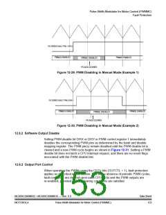
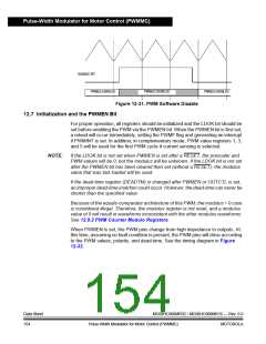
DISABLE BIT
PWM(S) ENABLED
PWM(S) DISABLED
PWM(S) ENABLED
Figure 12-31. PWM Software Disable
12.7 Initialization and the PWMEN Bit
For proper operation, all registers should be initialized and the LDOK bit should be
set before enabling the PWM via the PWMEN bit. When the PWMEN bit is first set,
a reload will occur immediately, setting the PWMF flag and generating an interrupt
if PWMINT is set. In addition, in complementary mode, PWM value registers 1, 3,
and 5 will be used for the first PWM cycle if current sensing is selected.
NOTE:
If the LDOK bit is not set when PWMEN is set after a RESET, the prescaler and
PWM values will be 0, but the modulus will be unknown. If the LDOK bit is not set
after the PWMEN bit has been cleared then set (without a RESET), the modulus
value that was last loaded will be used.
If the dead-time register (DEADTM) is changed after PWMEN or OUTCTL is set,
an improper dead-time insertion could occur. However, the dead-time can never be
shorter than the specified value.
Because of the equals-comparator architecture of this PWM, the modulus = 0 case
is considered illegal. Therefore, the modulus register is not reset, and a modulus
value of 0 will result in waveforms inconsistent with the other modulus waveforms.
See 12.9.2 PWM Counter Modulo Registers.
When PWMEN is set, the PWM pins change from high impedance to outputs. At
this time, assuming no fault condition is present, the PWM pins will drive according
to the PWM values, polarity, and dead-time. See the timing diagram in Figure
12-32.
Data Sheet
154
MC68HC908MR32 • MC68HC908MR16 — Rev. 6.0
Pulse-Width Modulator for Motor Control (PWMMC)
MOTOROLA

 FREESCALE [ Freescale ]