Pulse-Width Modulator for Motor Control (PWMMC)
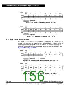
FILTERED FAULT PIN
PWM(S) ENABLED
PWM(S) ENABLED
PWM(S) DISABLED (INACTIVE)
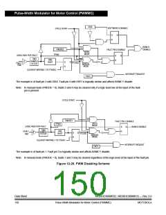
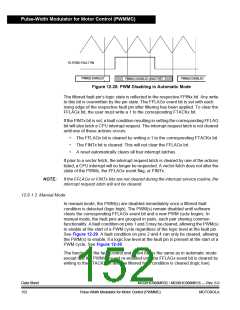
Figure 12-28. PWM Disabling in Automatic Mode
The filtered fault pin’s logic state is reflected in the respective FPINx bit. Any write
to this bit is overwritten by the pin state. The FFLAGx event bit is set with each
rising edge of the respective fault pin after filtering has been applied. To clear the
FFLAGx bit, the user must write a 1 to the corresponding FTACKx bit.
If the FINTx bit is set, a fault condition resulting in setting the corresponding FFLAG
bit will also latch a CPU interrupt request. The interrupt request latch is not cleared
until one of these actions occurs:
•
•
•
The FFLAGx bit is cleared by writing a 1 to the corresponding FTACKx bit.
The FINTx bit is cleared. This will not clear the FFLAGx bit.
A reset automatically clears all four interrupt latches.
If prior to a vector fetch, the interrupt request latch is cleared by one of the actions
listed, a CPU interrupt will no longer be requested. A vector fetch does not alter the
state of the PWMs, the FFLAGx event flag, or FINTx.
NOTE:
If the FFLAGx or FINTx bits are not cleared during the interrupt service routine, the
interrupt request latch will not be cleared.
12.6.1.3 Manual Mode
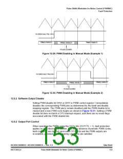
In manual mode, the PWM(s) are disabled immediately once a filtered fault
condition is detected (logic high). The PWM(s) remain disabled until software
clears the corresponding FFLAGx event bit and a new PWM cycle begins. In
manual mode, the fault pins are grouped in pairs, each pair sharing common
functionality. A fault condition on pins 1 and 3 may be cleared, allowing the PWM(s)
to enable at the start of a PWM cycle regardless of the logic level at the fault pin.
See Figure 12-29. A fault condition on pins 2 and 4 can only be cleared, allowing
the PWM(s) to enable, if a logic low level at the fault pin is present at the start of a
PWM cycle. See Figure 12-30.
The function of the fault control and event bits is the same as in automatic mode
except that the PWMs are not re-enabled until the FFLAGx event bit is cleared by
writing to the FTACKx bit and the filtered fault condition is cleared (logic low).
Data Sheet
152
MC68HC908MR32 • MC68HC908MR16 — Rev. 6.0
Pulse-Width Modulator for Motor Control (PWMMC)
MOTOROLA

 FREESCALE [ Freescale ]