Pulse-Width Modulator for Motor Control (PWMMC)
PWM Operation in Wait Mode
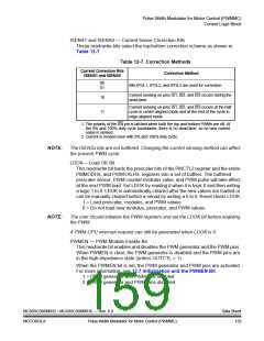
CPU CLOCK
PWMEN
DRIVE ACCORDING TO PWM
VALUE, POLARITY, AND DEAD-TIME
HI-Z IF OUTCTL = 0
PWM PINS
HI-Z IF OUTCTL = 0
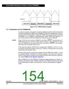
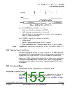
Figure 12-32. PWMEN and PWM Pins
When the PWMEN bit is cleared, this will occur:
•
•
•
PWM pins will be three-stated unless OUTCTL = 1.
PWM counter is cleared and will not be clocked.
Internally, the PWM generator will force its outputs to 0 to avoid glitches
when the PWMEN is set again.
When PWMEN is cleared, these features remain active:
•
•
•
All fault circuitry
Manual PWM pin control via the PWMOUT register
Dead-time insertion when PWM pins change via the PWMOUT register
NOTE:
The PWMF flag and pending CPU interrupts are NOT cleared when PWMEN = 0.
12.8 PWM Operation in Wait Mode
When the microcontroller is put in low-power wait mode via the WAIT instruction,
all clocks to the PWM module will continue to run. If an interrupt is issued from the
PWM module (via a reload or a fault), the microcontroller will exit wait mode.
Clearing the PWMEN bit before entering wait mode will reduce power consumption
in wait mode because the counter, prescaler divider, and LDFQ divider will no
longer be clocked. In addition, power will be reduced because the PWMs will no
longer toggle.
12.9 Control Logic Block
This subsection provides a description of the control logic block.
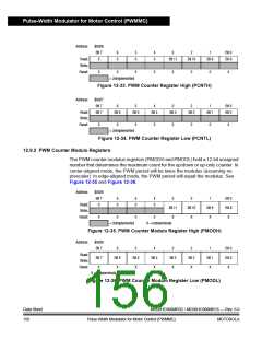
12.9.1 PWM Counter Registers
The PWM counter registers (PCNTH and PCNTL) display the 12-bit up/down or
up-only counter. When the high byte of the counter is read, the lower byte is
latched. PCNTL will hold this latched value until it is read. See Figure 12-33 and
Figure 12-34.
MC68HC908MR32 • MC68HC908MR16 — Rev. 6.0
MOTOROLA Pulse-Width Modulator for Motor Control (PWMMC)
Data Sheet
155

 FREESCALE [ Freescale ]