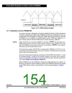
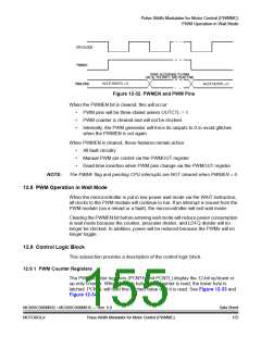
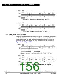
Pulse-Width Modulator for Motor Control (PWMMC)
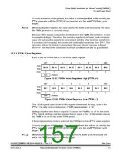
12.9.4 PWM Control Register 1
PWM control register 1 (PCTL1) controls PWM enabling/disabling, the loading of
new modulus, prescaler, PWM values, and the PWM correction method. In
addition, this register contains the software disable bits to force the PWM outputs
to their inactive states (according to the disable mapping register).
Address:
$0020
Bit 7
6
DISY
0
5
PWMINT
0
4
PWMF
0
3
ISENS1
0
2
ISENS0
0
1
LDOK
0
Bit 0
PWMEN
0
Read:
Write:
Reset:
DISX
0
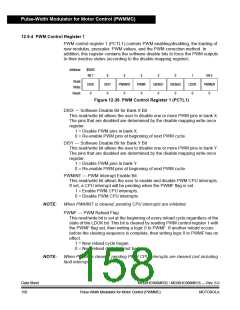
Figure 12-39. PWM Control Register 1 (PCTL1)
DISX — Software Disable Bit for Bank X Bit
This read/write bit allows the user to disable one or more PWM pins in bank X.
The pins that are disabled are determined by the disable mapping write-once
register.
1 = Disable PWM pins in bank X.
0 = Re-enable PWM pins at beginning of next PWM cycle.
DISY — Software Disable Bit for Bank Y Bit
This read/write bit allows the user to disable one or more PWM pins in bank Y.
The pins that are disabled are determined by the disable mapping write-once
register.
1 = Disable PWM pins in bank Y.
0 = Re-enable PWM pins at beginning of next PWM cycle.
PWMINT — PWM Interrupt Enable Bit
This read/write bit allows the user to enable and disable PWM CPU interrupts.
If set, a CPU interrupt will be pending when the PWMF flag is set.
1 = Enable PWM CPU interrupts.
0 = Disable PWM CPU interrupts.
NOTE:
When PWMINT is cleared, pending CPU interrupts are inhibited.
PWMF — PWM Reload Flag
This read/write bit is set at the beginning of every reload cycle regardless of the
state of the LDOK bit. This bit is cleared by reading PWM control register 1 with
the PWMF flag set, then writing a logic 0 to PWMF. If another reload occurs
before the clearing sequence is complete, then writing logic 0 to PWMF has no
effect.
1 = New reload cycle began.
0 = New reload cycle has not begun.
NOTE:
When PWMF is cleared, pending PWM CPU interrupts are cleared (not including
fault interrupts).
Data Sheet
158
MC68HC908MR32 • MC68HC908MR16 — Rev. 6.0
Pulse-Width Modulator for Motor Control (PWMMC)
MOTOROLA

 FREESCALE [ Freescale ]