Pulse-Width Modulator for Motor Control (PWMMC)
Control Logic Block
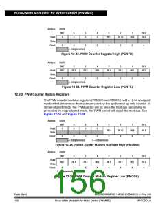
To avoid erroneous PWM periods, this value is buffered and will not be used by the
PWM generator until the LDOK bit has been set and the next PWM load cycle
begins.
NOTE:
When reading this register, the value read is the buffer (not necessarily the value
the PWM generator is currently using).
Because of the equals-comparator architecture of this PWM, the modulus = 0 case
is considered illegal. Therefore, the modulus register is not reset, and a modulus
value of 0 will result in waveforms inconsistent with the other modulus waveforms.
If a modulus of 0 is loaded, the counter will continually count down from $FFF. This
operation will not be tested or guaranteed (the user should consider it illegal).
However, the dead-time constraints and fault conditions will still be guaranteed.
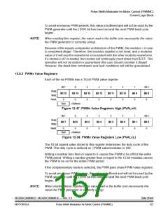
12.9.3 PWMx Value Registers
Each of the six PWMs has a 16-bit PWM value register.
Bit 7
6
5
Bit 13
0
4
Bit 12
0
3
Bit 11
0
2
Bit 10
0
1
Bit 9
0
Bit 0
Bit 8
0
Read:
Write:
Reset:
Bit 15
Bit 14
0
0
Bold
= Buffered
Figure 12-37. PWMx Value Registers High (PVALxH)
Bit 7
6
5
Bit 5
0
4
Bit 4
0
3
Bit 3
0
2
Bit 2
0
1
Bit 1
0
Bit 0
Bit 0
0
Read:
Write:
Reset:
Bit 7
Bit 6
0
0
Bold
= Buffered
Figure 12-38. PWMx Value Registers Low (PVALxL)
The 16-bit signed value stored in this register determines the duty cycle of the
PWM. The duty cycle is defined as: (PWM value/modulus) x 100.
Writing a number less than or equal to 0 causes the PWM to be off for the entire
PWM period. Writing a number greater than or equal to the 12-bit modulus causes
the PWM to be on for the entire PWM period.
If the complementary mode is selected, the PWM pairs share PWM value registers.
To avoid erroneous PWM pulses, this value is buffered and will not be used by the
PWM generator until the LDOK bit has been set and the next PWM load cycle
begins.
NOTE:
When reading these registers, the value read is the buffer (not necessarily the
value the PWM generator is currently using).
MC68HC908MR32 • MC68HC908MR16 — Rev. 6.0
MOTOROLA Pulse-Width Modulator for Motor Control (PWMMC)
Data Sheet
157

 FREESCALE [ Freescale ]