Pulse-Width Modulator for Motor Control (PWMMC)
Fault Protection
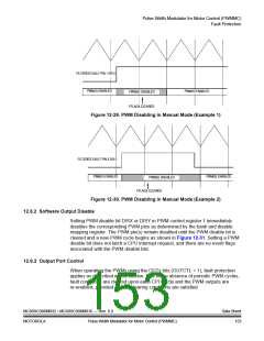
FILTERED FAULT PIN 1 OR 3
PWM(S) ENABLED
PWM(S) ENABLED
PWM(S) DISABLED
FFLAGX CLEARED
Figure 12-29. PWM Disabling in Manual Mode (Example 1)
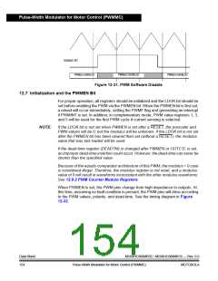
FILTERED FAULT PIN 2 OR 4
PWM(S) ENABLED
PWM(S) ENABLED
PWM(S) DISABLED
FFLAGX CLEARED
Figure 12-30. PWM Disabling in Manual Mode (Example 2)
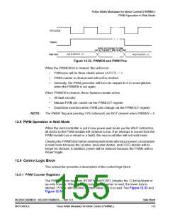
12.6.2 Software Output Disable
Setting PWM disable bit DISX or DISY in PWM control register 1 immediately
disables the corresponding PWM pins as determined by the bank and disable
mapping register. The PWM pin(s) remain disabled until the PWM disable bit is
cleared and a new PWM cycle begins as shown in Figure 12-31. Setting a PWM
disable bit does not latch a CPU interrupt request, and there are no event flags
associated with the PWM disable bits.
12.6.3 Output Port Control
When operating the PWMs using the OUTx bits (OUTCTL = 1), fault protection
applies as described in this section. Due to the absence of periodic PWM cycles,
fault conditions are cleared upon each CPU cycle and the PWM outputs are
re-enabled, provided all fault clearing conditions are satisfied.
MC68HC908MR32 • MC68HC908MR16 — Rev. 6.0
MOTOROLA Pulse-Width Modulator for Motor Control (PWMMC)
Data Sheet
153

 FREESCALE [ Freescale ]