Pulse-Width Modulator for Motor Control (PWMMC)
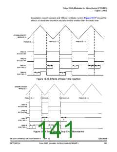
UP/DOWN COUNTER
MOUDULUS = 3
PWM VALUE = 2
PWM VALUE = 3
PWM VALUE = 2
PWM VALUE = 1
PWM1 W/
NO DEAD-TIME
PWM2 W/
NO DEAD-TIME
PWM1 W/
3
3
3
DEAD-TIME = 3
PWM2 W/
DEAD-TIME = 3
3
3
3
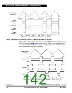
Figure 12-17. Dead-Time and Small Pulse Widths
12.5.3 Top/Bottom Correction with Motor Phase Current Polarity Sensing
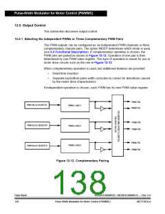
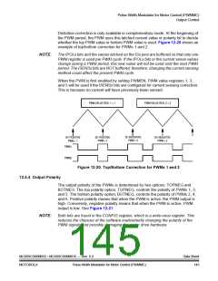
Ideally, when complementary pairs are used, the PWM pairs are inversions of each
other, as shown in Figure 12-18. When PWM1 is active, PWM2 is inactive, and
vice versa. In this case, the motor terminal voltage is never allowed to float and is
strictly controlled by the PWM waveforms.
UP/DOWN COUNTER
MODULUS = 4
PWM1
PWM VALUE = 1
PWM2
PWM3
PWM VALUE = 2
PWM4
PWM5
PWM VALUE = 3
PWM6
Figure 12-18. Ideal Complementary Operation (Dead-Time = 0)
Data Sheet
142
MC68HC908MR32 • MC68HC908MR16 — Rev. 6.0
Pulse-Width Modulator for Motor Control (PWMMC)
MOTOROLA

 FREESCALE [ Freescale ]