Pulse-Width Modulator for Motor Control (PWMMC)
Output Control
PWM
3
PWM
1
PWM
5
TO
AC
MOTOR
INPUTS
PWM
2
PWM
4
PWM
6
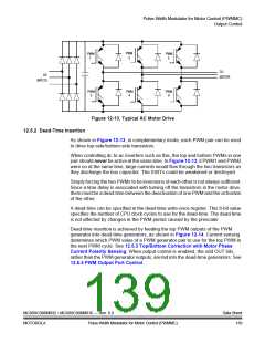
Figure 12-13. Typical AC Motor Drive
12.5.2 Dead-Time Insertion
As shown in Figure 12-13, in complementary mode, each PWM pair can be used
to drive top-side/bottom-side transistors.
When controlling dc-to-ac inverters such as this, the top and bottom PWMs in one
pair should never be active at the same time. In Figure 12-13, if PWM1 and PWM2
were on at the same time, large currents would flow through the two transistors as
they discharge the bus capacitor. The IGBTs could be weakened or destroyed.
Simply forcing the two PWMs to be inversions of each other is not always sufficient.
Since a time delay is associated with turning off the transistors in the motor drive,
there must be a dead-time between the deactivation of one PWM and the activation
of the other.
A dead-time can be specified in the dead-time write-once register. This 8-bit value
specifies the number of CPU clock cycles to use for the dead-time. The dead-time
is not affected by changes in the PWM period caused by the prescaler.
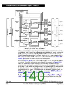
Dead-time insertion is achieved by feeding the top PWM outputs of the PWM
generator into dead-time generators, as shown in Figure 12-14. Current sensing
determines which PWM value of a PWM generator pair to use for the top PWM in
the next PWM cycle. See 12.5.3 Top/Bottom Correction with Motor Phase
Current Polarity Sensing. When output control is enabled, the odd OUT bits,
rather than the PWM generator outputs, are fed into the dead-time generators. See
12.5.5 PWM Output Port Control.
MC68HC908MR32 • MC68HC908MR16 — Rev. 6.0
MOTOROLA Pulse-Width Modulator for Motor Control (PWMMC)
Data Sheet
139

 FREESCALE [ Freescale ]