Pulse-Width Modulator for Motor Control (PWMMC)
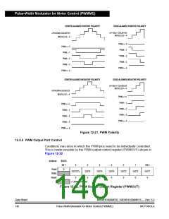
CENTER-ALIGNED POSITIVE POLARITY
EDGE-ALIGNED POSITIVE POLARITY
UP-ONLY COUNTER
MODULUS = 4
UP/DOWN COUNTER
MODULUS = 4
PWM <= 0
PWM = 1
PWM = 2
PWM = 3
PWM >= 4
PWM <= 0
PWM = 1
PWM = 2
PWM = 3
PWM >= 4
CENTER-ALIGNED NEGATIVE POLARITY
EDGE-ALIGNED NEGATIVE POLARITY
UP-ONLY COUNTER
MODULUS = 4
UP/DOWN COUNTER
MODULUS = 4
PWM <= 0
PWM = 1
PWM = 2
PWM = 3
PWM >= 4
PWM <= 0
PWM = 1
PWM = 2
PWM = 3
PWM >= 4
Figure 12-21. PWM Polarity
12.5.5 PWM Output Port Control
Conditions may arise in which the PWM pins need to be individually controlled.
This is made possible by the PWM output control register (PWMOUT) shown in
Figure 12-22.
Address:
$0025
Bit 7
0
6
OUTCTL
0
5
OUT6
0
4
OUT5
0
3
OUT4
0
2
OUT3
0
1
OUT2
0
Bit 0
OUT1
0
Read:
Write:
Reset:
0
= Unimplemented
Figure 12-22. PWM Output Control Register (PWMOUT)
Data Sheet
146
MC68HC908MR32 • MC68HC908MR16 — Rev. 6.0
Pulse-Width Modulator for Motor Control (PWMMC) MOTOROLA

 FREESCALE [ Freescale ]