Pulse-Width Modulator for Motor Control (PWMMC)
12.5 Output Control
This subsection discusses output control.
12.5.1 Selecting Six Independent PWMs or Three Complementary PWM Pairs
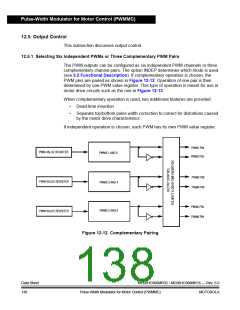
The PWM outputs can be configured as six independent PWM channels or three
complementary channel pairs. The option INDEP determines which mode is used
(see 5.2 Functional Description). If complementary operation is chosen, the
PWM pins are paired as shown in Figure 12-12. Operation of one pair is then
determined by one PWM value register. This type of operation is meant for use in
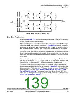
motor drive circuits such as the one in Figure 12-13.
When complementary operation is used, two additional features are provided:
•
•
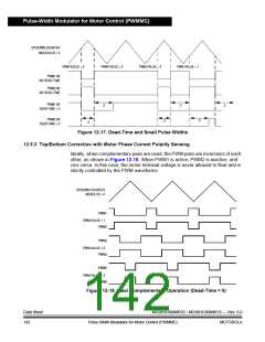
Dead-time insertion
Separate top/bottom pulse width correction to correct for distortions caused
by the motor drive characteristics
If independent operation is chosen, each PWM has its own PWM value register.
PWM1 PIN
PWM VALUE REGISTER
PWMS 1 AND 2
PWM2 PIN
PWM3 PIN
PWM4 PIN
PWM VALUE REGISTER
PWMS 3 AND 4
PWM5 PIN
PWM6 PIN
PWMS 5 AND 6
PWM VALUE REGISTER
Figure 12-12. Complementary Pairing
Data Sheet
138
MC68HC908MR32 • MC68HC908MR16 — Rev. 6.0
Pulse-Width Modulator for Motor Control (PWMMC) MOTOROLA

 FREESCALE [ Freescale ]