Pulse-Width Modulator for Motor Control (PWMMC)
Output Control
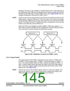
Distortion correction is only available in complementary mode. At the beginning of
the PWM period, the PWM uses this latched current value or polarity bit to decide
whether the top PWM value or bottom PWM value is used. Figure 12-20 shows an
example of top/bottom correction for PWMs 1 and 2.
NOTE:
The IPOLx bits and the values latched on the ISx pins are buffered so that only one
PWM register is used per PWM cycle. If the IPOLx bits or the current sense values
change during a PWM period, this new value will not be used until the next PWM
period. The ISENSx bits are NOT buffered; therefore, changing the current sensing
method could affect the present PWM cycle.
When the PWM is first enabled by setting PWMEN, PWM value registers 1, 3,
and 5 will be used if the ISENSx bits are configured for current sensing correction.
This is because no current will have previously been sensed.
PWM VALUE REG. 1 = 1
PWM VALUE REG. 2 = 2
IS1 NEGATIVE
PWM = 2
IS1 POSITIVE
PWM = 1
IS1 POSITIVE
PWM = 1
IS1 NEGATIVE
PWM = 2
PWM1
PWM2
Figure 12-20. Top/Bottom Correction for PWMs 1 and 2
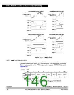
12.5.4 Output Polarity
The output polarity of the PWMs is determined by two options: TOPNEG and
BOTNEG. The top polarity option, TOPNEG, controls the polarity of PWMs 1, 3,
and 5. The bottom polarity option, BOTNEG, controls the polarity of PWMs 2, 4,
and 6. Positive polarity means that when the PWM is active, the PWM output is
high. Conversely, negative polarity means that when the PWM is active, PWM
output is low. See Figure 12-21.
NOTE:
Both bits are found in the CONFIG register, which is a write-once register. This
reduces the chances of the software inadvertently changing the polarity of the
PWM signals and possibly damaging the motor drive hardware.
MC68HC908MR32 • MC68HC908MR16 — Rev. 6.0
MOTOROLA Pulse-Width Modulator for Motor Control (PWMMC)
Data Sheet
145

 FREESCALE [ Freescale ]