Pulse-Width Modulator for Motor Control (PWMMC)
Output Control
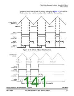
However, when dead-time is inserted, the motor voltage is allowed to float
momentarily during the dead-time interval, creating a distortion in the motor current
waveform. This distortion is aggravated by dissimilar turn-on and turn-off delays of
each of the transistors.
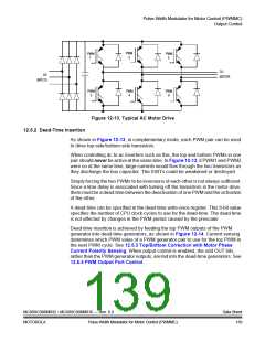
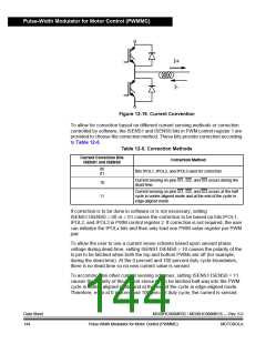
For a typical motor drive inverter as shown in Figure 12-13, for a given top/bottom
transistor pair, only one of the transistors will be effective in controlling the output
voltage at any given time depending on the direction of the motor current for that
pair. To achieve distortion correction, one of two different correction factors must
be added to the desired PWM value, depending on whether the top or bottom
transistor is controlling the output voltage. Therefore, the software is responsible
for calculating both compensated PWM values and placing them in an odd/even
PWM register pair. By supplying the PWM module with information regarding which
transistor (top or bottom) is controlling the output voltage at any given time (for
instance, the current polarity for that motor phase), the PWM module selects either
the odd or even numbered PWM value register to be used by the PWM generator.
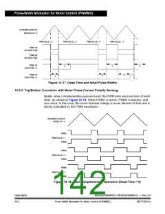
Current sensing or programmable software bits are then used to determine which
PWM value to use. If the current sensed at the motor for that PWM pair is positive
(voltage on current pin ISx is low) or bit IPOLx in PWM control register 2 is low, the
top PWM value is used for the PWM pair. Likewise, if the current sensed at the
motor for that PWM pair is negative (voltage on current pin ISx is high) or bit IPOLx
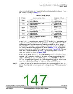
in PWM control register 2 is high, the bottom PWM value is used. See Table 12-4.
NOTE:
This text assumes the user will provide current sense circuitry which causes the
voltage at the corresponding input pin to be low for positive current and high for
negative current. See Figure 12-19 for current convention. In addition, it assumes
the top PWMs are PWMs 1, 3, and 5 while the bottom PWMs are PWMs 2, 4, and 6.
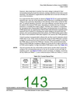
Table 12-4. Current Sense Pins
Voltage
Current
on Current
Sense Pin
PWM Value
Register Used
PWMs
Affected
Sense Pin
or Bit
or IPOLx Bit
IS1 or IPOL1
IS1 or IPOL1
Logic 0
Logic 1
PWM value register 1
PWM value register 2
PWMs 1 and 2
PWMs 1 and 2
MC68HC908MR32 • MC68HC908MR16 — Rev. 6.0
MOTOROLA Pulse-Width Modulator for Motor Control (PWMMC)
Data Sheet
143

 FREESCALE [ Freescale ]