Pulse-Width Modulator for Motor Control (PWMMC)
Output Control
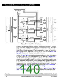
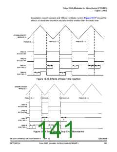
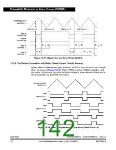
boundaries (near 0 percent and 100 percent duty cycles). Figure 12-17 shows the
effects of dead-time insertion on pulse widths smaller than the dead-time.
UP/DOWN COUNTER
MODULUS = 4
PWM VALUE = 2
PWM VALUE = 3
PWM VALUE = 2
PWM1 W/
NO DEAD-TIME
PWM2 W/
NO DEAD-TIME
PWM1 W/
DEAD-TIME = 2
2
2
2
2
PWM2 W/
DEAD-TIME = 2
2
2
Figure 12-15. Effects of Dead-Time Insertion
UP/DOWN COUNTER
MODULUS = 3
PWM VALUE = 1
PWM VALUE = 1
PWM VALUE = 3
PWM VALUE = 3
PWM1 W/
NO DEAD-TIME
PWM2 W/
NO DEAD-TIME
PWM1 W/
DEAD-TIME = 2
2
2
PWM2 W/
DEAD-TIME = 2
2
2
Figure 12-16. Dead-Time at Duty Cycle Boundaries
MC68HC908MR32 • MC68HC908MR16 — Rev. 6.0
MOTOROLA Pulse-Width Modulator for Motor Control (PWMMC)
Data Sheet
141

 FREESCALE [ Freescale ]