Pulse-Width Modulator for Motor Control (PWMMC)
OUTPUT CONTROL
(OUTCTL)
OUT2
OUT4
OUT6
MUX
PWMPAIR12
TOP
PWM1
PWM2
PWM (TOP)
(TOP)
(PWM1)
DEAD-TIME
POSTDT (TOP)
PREDT (TOP)
OUTX
BOTTOM
(PWM2)
SELECT
MUX
PWMPAIR34
(TOP)
TOP
(PWM3)
PWM (TOP)
PWM3
PWM4
DEAD-TIME
POSTDT (TOP)
PREDT (TOP)
OUTX
BOTTOM
(PWM4)
SELECT
6
MUX
PWMPAIR56
(TOP)
TOP
(PWM5)
PWM (TOP)
PWM5
PWM6
DEAD-TIME
POSTDT (TOP)
PREDT (TOP)
OUTX
BOTTOM
(PWM6)
SELECT
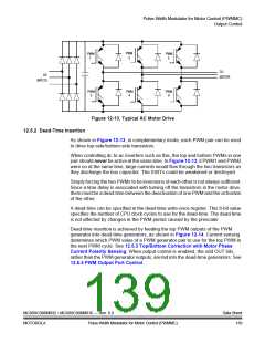
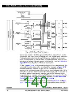
Figure 12-14. Dead-Time Generators
Whenever an input to a dead-time generator transitions, a dead-time is inserted
(for example, both PWMs in the pair are forced to their inactive state). The bottom
PWM signal is generated from the top PWM and the dead-time. In the case of
output control enabled, the odd OUTx bits control the top PWMs, the even OUTx
bits control the bottom PWMs with respect to the odd OUTx bits (see Table 12-6).
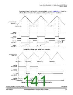
Figure 12-15 shows the effects of the dead-time insertion.
As seen in Figure 12-15, some pulse width distortion occurs when the dead-time
is inserted. The active pulse widths are reduced. For example, in Figure 12-15,
when the PWM value register is equal to two, the ideal waveform (with no
dead-time) has pulse widths equal to four. However, the actual pulse widths shrink
to two after a dead-time of two was inserted. In this example, with the prescaler set
to divide by one and center-aligned operation selected, this distortion can be
compensated for by adding or subtracting half the dead-time value to or from the
PWM register value. This correction is further described in 12.5.3 Top/Bottom
Correction with Motor Phase Current Polarity Sensing.
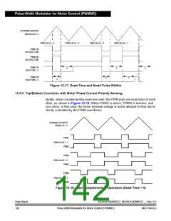
Further examples of dead-time insertion are shown in Figure 12-16 and Figure
12-17. Figure 12-16 shows the effects of dead-time insertion at the duty cycle
Data Sheet
140
MC68HC908MR32 • MC68HC908MR16 — Rev. 6.0
Pulse-Width Modulator for Motor Control (PWMMC)
MOTOROLA

 FREESCALE [ Freescale ]