Pulse-Width Modulator for Motor Control (PWMMC)
I+
I-
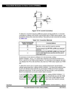
Figure 12-19. Current Convention
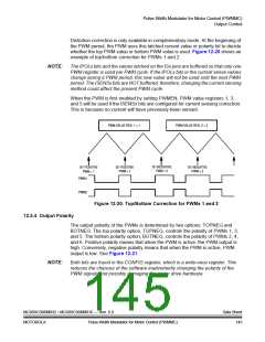
To allow for correction based on different current sensing methods or correction
controlled by software, the ISENS1 and ISENS0 bits in PWM control register 1 are
provided to choose the correction method. These bits provide correction according
to Table 12-5.
Table 12-5. Correction Methods
Current Correction Bits
Correction Method
ISENS1 and ISENS0
00
Bits IPOL1, IPOL2, and IPOL3 used for correction
01
Current sensing on pins IS1, IS2, and IS3 occurs during the
dead-time.
10
Current sensing on pins IS1, IS2, and IS3 occurs at the half
11
cycle in center-aligned mode and at the end of the cycle in
edge-aligned mode.
If correction is to be done in software or is not necessary, setting
ISENS1:ISENS0 = 00 or = 01 causes the correction to be based on bits IPOL1,
IPOL2, and IPOL3 in PWM control register 2. If correction is not required, the user
can initialize the IPOLx bits and then only load one PWM value register per PWM
pair.
To allow the user to use a current sense scheme based upon sensed phase
voltage during dead-time, setting ISENS1:ISENS0 = 10 causes the polarity of the
Ix pin to be latched when both the top and bottom PWMs are off (for example,
during the dead-time). At the 0 percent and 100 percent duty cycle boundaries,
there is no dead-time so no new current value is sensed.
To accommodate other current sensing schemes, setting ISENS1:ISENS0 = 11
causes the polarity of the current sense pin to be latched half-way into the PWM
cycle in center-aligned mode and at the end of the cycle in edge-aligned mode.
Therefore, even at 0 percent and 100 percent duty cycle, the current is sensed.
Data Sheet
144
MC68HC908MR32 • MC68HC908MR16 — Rev. 6.0
Pulse-Width Modulator for Motor Control (PWMMC)
MOTOROLA

 FREESCALE [ Freescale ]