Pulse-Width Modulator for Motor Control (PWMMC)
PWM Generators
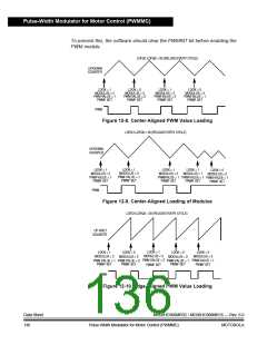
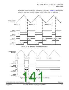
LDFQ1:LDFQ0 = 00 (RELOAD EVERY CYCLE)
UP-ONLY
COUNTER
LDOK = 1
LDOK = 1
MODULUS = 4
PWM VALUE = 2
PWMF SET
LDOK = 0
MODULUS = 1
PWM VALUE = 2
PWMF SET
LDOK = 1
MODULUS = 3
PWM VALUE = 2
PWMF SET
MODULUS = 2
PWM VALUE = 2
PWMF SET
PWM
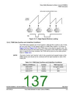
Figure 12-11. Edge-Aligned Modulus Loading
12.4.2 PWM Data Overflow and Underflow Conditions
The PWM value registers are 16-bit registers. Although the counter is only 12 bits,
the user may write a 16-bit signed value to a PWM value register. As shown in
Figure 12-4 and Figure 12-5, if the PWM value is less than or equal to zero, the
PWM will be inactive for the entire period. Conversely, if the PWM value is greater
than or equal to the timer modulus, the PWM will be active for the entire period.
Refer to Table 12-3.
NOTE:
The terms “active” and “inactive” refer to the asserted and negated states of the
PWM signals and should not be confused with the high-impedance state of the
PWM pins.
Table 12-3. PWM Data Overflow and Underflow Conditions
PWMVALxH:PWMVALxL
$0000–$0FFF
Condition
Normal
PWM Value Used
Per register contents
$FFF
$1000–$7FFF
Overflow
Underflow
$8000–$FFFF
$000
MC68HC908MR32 • MC68HC908MR16 — Rev. 6.0
MOTOROLA Pulse-Width Modulator for Motor Control (PWMMC)
Data Sheet
137

 FREESCALE [ Freescale ]