Freescale Semiconductor, Inc.
Analog-to-Digital Converter
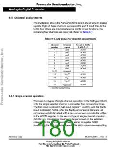
9.5 Channel assignments
The multiplexer allows the A/D converter to select one of sixteen analog
signals. Eight of these channels correspond to port E input lines to the
MCU, four others are internal reference points or test functions; the
remaining four channels are reserved. Refer to Table 9-1.
Table 9-1. A/D converter channel assignments
Channel
number
Channel
signal
Result in ADRx
if MULT = 1
1
AN0
AN1
ADR1
ADR2
ADR3
ADR4
ADR1
ADR2
ADR3
ADR4
—
2
3
AN2
4
AN3
5
6
AN4
AN5
7
AN6
8
AN7
9–12
reserved
(1)
13
14
15
16
ADR1
ADR2
ADR3
ADR4
VRH
*
VRL
V
RH/2*
reserved*
1. Used for factory testing.
9.5.1 Single-channel operation
There are two types of single-channel operation. In the first type (SCAN
= 0), the single selected channel is converted four consecutive times.
The first result is stored in A/D result register 1 (ADR1), and the fourth
result is stored in ADR4. After the fourth conversion is complete, all
conversion activity is halted until a new conversion command is written
to the ADCTL register. In the second type of single-channel operation
(SCAN = 1), conversions continue to be performed on the selected
channel with the fifth conversion being stored in register ADR1
(overwriting the first conversion result), the sixth conversion overwriting
Technical Data
MC68HC11P2 — Rev 1.0
Analog-to-Digital Converter
For More Information On This Product,
Go to: www.freescale.com

 FREESCALE [ Freescale ]