Freescale Semiconductor, Inc.
Analog-to-Digital Converter
Control, status and results registers
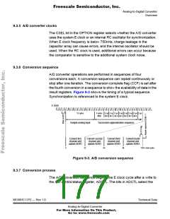
9.5.2 Multiple-channel operation
There are two types of multiple-channel operation. In the first type
(SCAN = 0), a selected group of four channels is converted once only.
The first result is stored in A/D result register 1 (ADR1), and the fourth
result is stored in ADR4. After the fourth conversion is complete, all
conversion activity is halted until a new conversion command is written
to the ADCTL register. In the second type of multiple-channel operation
(SCAN = 1), conversions continue to be performed on the selected
group of channels with the fifth conversion being stored in register ADR1
(replacing the earlier conversion result for the first channel in the group),
the sixth conversion overwriting ADR2, and so on.
9.6 Control, status and results registers
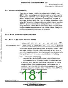
9.6.1 ADCTL — A/D control and status register
State
on reset
Address bit 7 bit 6 bit 5 bit 4 bit 3 bit 2 bit 1 bit 0
A/D control & status (ADCTL)
$0030 CCF SCAN MULT CD CC CB CA u0uu uuuu
0
All bits in this register can be read or written, except bit 7, which is a read-
only status indicator, and bit 6, which always reads as zero. Write to
ADCTL to initiate a conversion. To quit a conversion in progress, write to
this register and a new conversion sequence begins immediately.
CCF — Conversions complete flag
1 = All four A/D result registers contain valid conversion data.
0 = At least one of the A/D result registers contains invalid data.
A read-only status indicator, this bit is set when all four A/D result
registers contain valid conversion results. Each time the ADCTL
register is overwritten, this bit is automatically cleared to zero and a
conversion sequence is started. In the continuous mode, CCF is set
at the end of the first conversion sequence.
Bit 6 — Not implemented; always reads zero.
MC68HC11P2 — Rev 1.0
Technical Data
Analog-to-Digital Converter
For More Information On This Product,
Go to: www.freescale.com

 FREESCALE [ Freescale ]